Extending MoveIt with hand-eye calibration #1070
Comments
|
There is nothing in MoveIt to my knowledge, but I remember the easy-handeye package that was presented at ROSCon last year (video). It was apparently not easy enough for 5 different researchers that I have proposed it to, so there is room for improvement. |
|
@felixvd Thanks for your feedback! I think it's necessary to add this new tool in MoveIt, because as I know, for some groups who are from AI perception and want to deliver solutions to the robot arm apps, they met some difficulty of getting the precise camera and robot transform when they try to do some experiments with ROS and MoveIt. |
|
I can confirm that it is still a challenge for many non-computer-vision people to determine the position of a camera, so your efforts are welcome. Just be aware of this and this and keep it simple. It is a good idea to start by making something you want to use yourself, instead of something you think others might want to use. The latter invites feature creep, and nothing beats simplicity and good defaults when it comes to usability for newcomers. Good luck. |
|
@felixvd Thanks for your advice! 😄 |
|
@RoboticsYY I like this idea to make calibration easier to setup in the MoveIt! Setup Assistant! Thoughts:
|
|
@davetcoleman Thanks for your feedback!
Currently, I split the calibration process into four steps:
In my current design, I only provide one option for the calibration solver: handeye. I have done a benchmark test in the simulation to the available calibrators I can find, it seems that this calibrator has the good performance in the translation error and rotation error compared to the others. visp_hand2eye_calibration also has good performance, but the license is a problem. The solver is called through a ROS service.
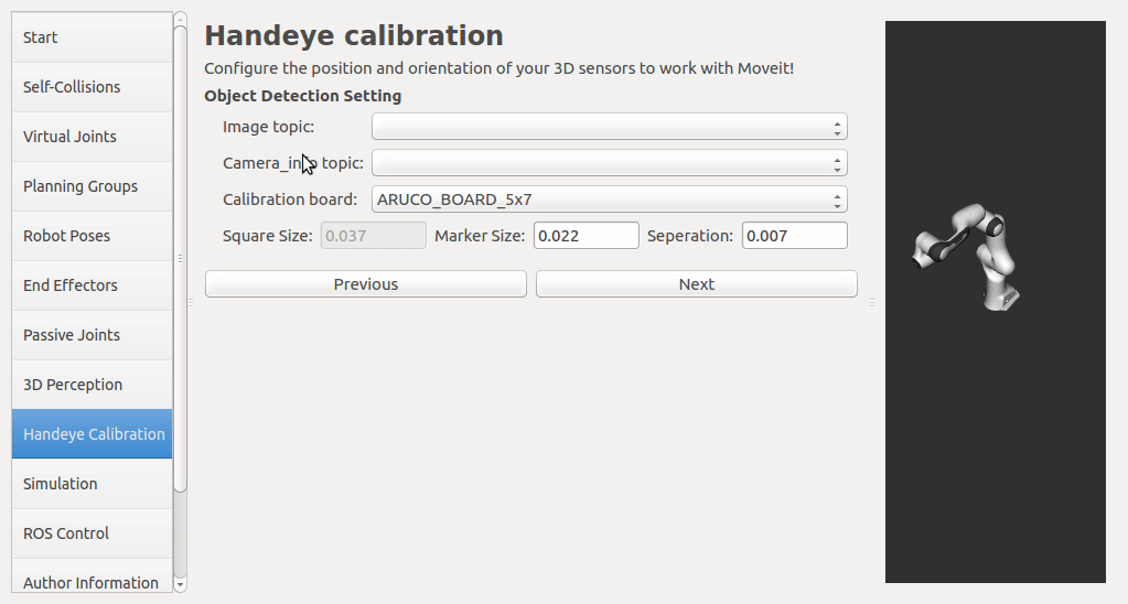
If a rgbd camera, stereo camera or a normal usb camera is used, six default opencv calibration patterns are provided. I plan to put the default patterns in the tutorial, so that there is no need to create them, just download and print. User has to set up the rgb image topic and the corresponding camera info topic from the pop up list. The topic type filter is implemented. Once a calibration pattern is selected, the precise size of the marker or black square or the marker separation distance is required to fill in. Since the calibration will look up TF information, other patterns than the default ones can be used by choosing
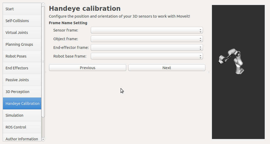
The calibration will look up the TFs of them.
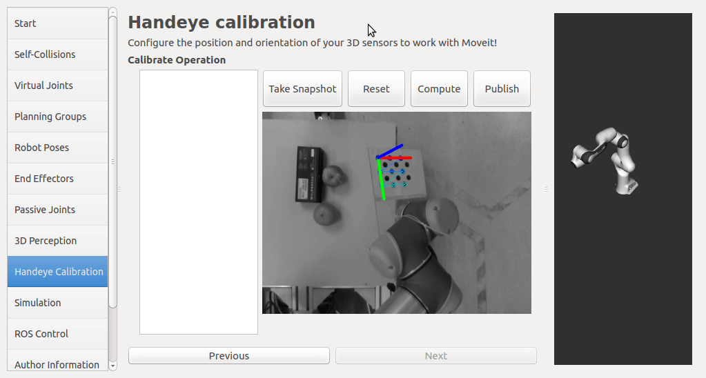
In this step, user can take samples of the required transforms by clicking Right now, I'm also adding some functions to limit user's random inputs. Welcome any comments or suggestions! |
|
This is pretty impressive progress! I'm curious what input @drchrislewis might have given he's worked on similar stuff recently as presented at ROSCon 2018. The one big architectural question I have is... does this advanced functionality belong in the MSA or should it be a standone application? The fact that it generates a |
|
@davetcoleman @RoboticsYY This is quite interesting to me. I just recently refactored my calibration routines into something with a very similar look and feel. One of the calibrations available is the eye-hand or what I've called wrist-cal. I created two rviz plugins, a bit crude, but similar to the operation of what is presented here. My calibration nodes are now service call operated. This allows the robot teach pendant code to execute them without requiring MoveIt! Some companies still don't want to relinquish control of the robot motion to an automated path planner. One service call is for reset to eliminate any previously collected data, one for taking observations, one for running the optimization, one for saving the data, and one for computing the covariance. The same interface is available for intrinsic calibration, stereo calibration, and wrist calibration. Another node that is very useful is one that creates, stores and executes a set of poses where it stops pauses and collects the data at each pose. The nice thing about the setup assistant you made is that the launch files that I have to create to define the necessary transforms and targets are defined using a GUI rather than editing a yaml file. I have a couple of warnings for you though. Our next goal is to provide robot kinematic calibration. I'm not sure when we'll get time to work on this though. I've got several projects that are in dire need of it. Please keep me informed of any new work on this. Thanks |
|
@davetcoleman Thanks for your questions! In my humble opinion, maybe this is more suitable for MSA. I think, in usual cases, once the camera and its installation is determined, it is not frequently changed for a specific application, which is like the situation of the end-effector. If the location of the camera needs to be adjusted, there is no need to make the configuration again, the parameters will be loaded from the pre-configured yaml file. User only needs to spend a few minutes to calibrate again, or if the joint goals were recorded, this could be automatic for the second time. Then the result will be kept until the design of app changes or the camera is moved for some accident reason. And I also think that maybe it’s better to determine the location of camera before using the robot to make motion planning, since the environment scanning and octomap depends on it. In addition, I try to keep this handeye tool as simple as possible. Suppose there is a calibration pipeline as a standalone app in MoveIt!, maybe we also need a screen in MSA to provide some assistance for setting up the configurations of the calibration. @drchrislewis Thanks for your feedback and introductions to the notable technique points in the calibration process! I agree with you and I believe that As @felixvd indicated, there is some gap between the user and the calibration expert. Maybe we can find better ideas from this discussion. |
|
I'm discussing this effort with @RoboticsYY and his team in China today and in summary:
|
|
@davetcoleman Hi, may I know if this feature is still planned to be released with MoveIt 1.0 in March? |
|
@athish-t The code and tutorial is planned to be public in March and a PR will be submitted. Seems API is frozen before April, I think it cannot catch up with MoveIt! 1.0. |
|
In the next week we should have a new |
Architecture redesignRecently the hand-eye calibration tool was redesigned. The previous design has some drawbacks:
Now the new hand-eye tool is plugin based, it contains three plugins:
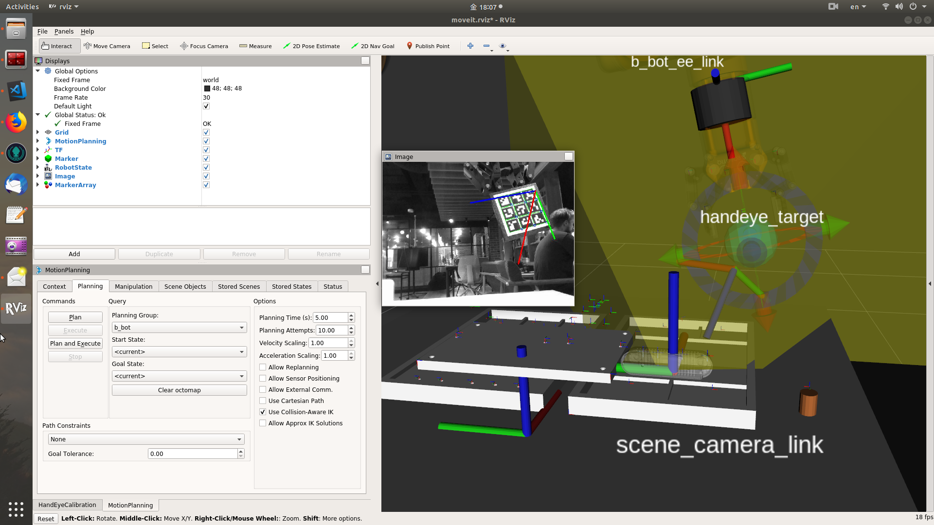
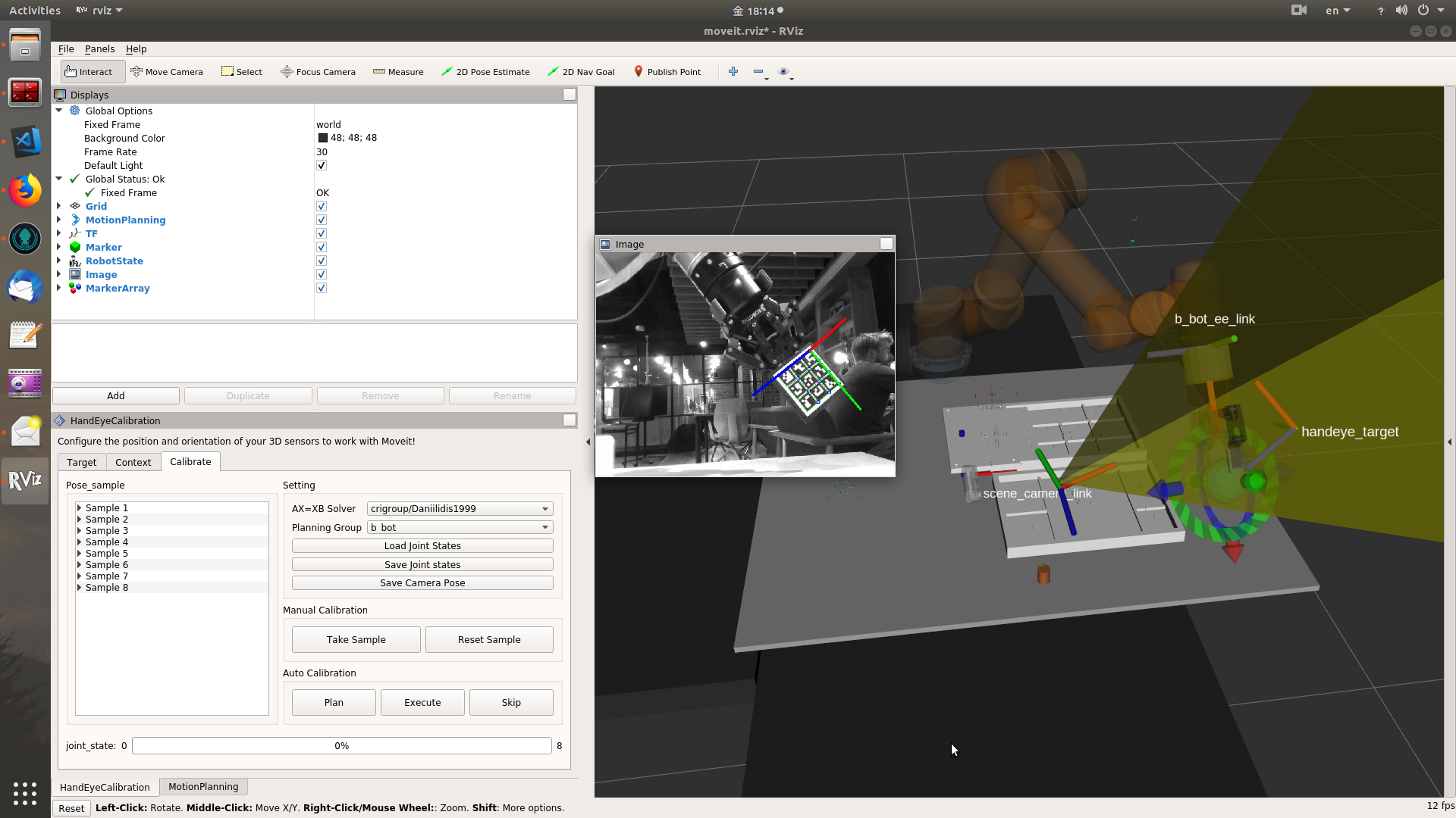
Interface introductionThe Rviz GUI plugin contains three tabs widgets, which contains separate functions. First tab widgetOn the first tab widget, user can load available target plugin, create target with necessary parameters. We are using parameters that are general to most kinds of calibration board, so that a new target detection plugin can reuse the parameters. The created target can be displayed and saved. When doing the target detection, the camera image topic and camera info topic can be selected from topic filtered combobox. And the real size and separation distance of markers in the target can be set by user. Second tab widgetOn the second tab widget, user can select sensor mount type, "eye-in-hand" or "eye-to-hand". Four frame names necessary for a hand-eye calibration can be selected from available TF frames. We also allow user to set an initial guess pose of the camera. The four selected frames and the camera FOV can also be displayed. The FOV is generated from the received CameraInfo message. Third tab widgetOn the third tab widget, user can select solver from the loaded solver plugins. This tab separates into manual calibration and auto calibration.
Some summary
|


|
Looks great. Looking forward to testing the PRs. |
|
Having an easy to use eye-hand calibration is definitely worth the effort. This seems to duplicate some of my work, available in industrial_calibration. I won't say I got it right. I do have a few comments.
|
|
@drchrislewis Thanks for your comments! My effort intends to develop an flexible and easy-to-use hand-eye calibration tool, and mainly focus on two directions:
I agree with you that OpenCV target detection is not the best choice for hand-eye calibration. Here I only provide it as a default plugin, other target detection algorithm can also be used as a plugin here and collects parameters from the GUI. The reason I use OpenCV because it comes as a default installation with ROS, which is easy to compile against.
I provide an AX=XB library as a default plugin. But other algorithm can also works as a plugin here. Actually, the functions of setting the initial guess pose of a camera developed on GUI is ready for some iterative calibration algorithms other than the AX=XB algorithms. The GUI only works as data collection here. Maybe the "AX=XB Solver" label on the third tab widget make some confusion, I will change the name.
I agree that other calibrations are also important for industrial robots. Here my work only focus on the hand-eye calibration problem. But it is also possible to add the other calibration functions as new tab widgets on the panel, if this tool is proved necessary to become an fully functional calibration tool.
In my design, the pose of a camera is displayed as a coordinate axis marker, and it is updated when TF system is updated. The 3D model of a camera is not considered in the calibration process. The calibration result is used as a .launch file.
In my current version, a covariance estimation is not added yet.
The tool works in a similar way. The joint poses are recorded into a .yaml file when user makes a manual calibration with a teach pendent. User can load these joint poses back, and plan and execute them, or skip any one of them.
Actually, I don't implement any method to automatically generate a set of poses with the kinematics computation. In my opinion, there are some pros and cons for doing this. It truly brings some convenience of automation, but also brings some risks and complexity that may not be suitable for some non-professional users. |
|
If I may add as an outsider (I was not personally responsible for camera calibration in my past robot projects, but I noticed people were struggling and I could not point them to a package that was simple enough to use for them. I have also never heard about the industrial_calibration package):
I remember that the orientation of checkerboard patterns can flip between images too, causing the markers to be misordered.
Could you explain why this is set up in this way, and what you mean by "merge the robot joint states with a set of mutable joint states"? Why would this sort of update be automatic and persistent, but not e.g. a TF publisher?
Great idea too, +1 |
|
@felixvd We felt that one would like the extrinsic calibration parameters should act in a way similar to the intrinsic parameters of a camera info manager. The camera info manager reads a file, publishes the intrinsics, and can accept updates. Once the updates are written, the next time the camera node is launched the updated values are retained. TF does not have this in native form. It does have a floating transform, but MoveIt! did not support it at the time we wrote our code. Instead, we created a mutable_joint_states node that reads the joint values from a file, and publishes them as joint_states so that MoveIt can work with them and so that obstacle avoidance will avoid collisions with the camera even after one changes the extrinsic calibration. For this to work, one needs to combine the robot joint states with the ones we publish into a single topic called joint_states. The robot state publisher I believe requires it. Once its all set up, one can call a service an manually adjust the extrinsic calibration until it is approximately correct. MoveIt works fine to avoid camera collisions etc. Then one can run the calibration, once the new values are computed, and updated, the save service is called, and the original yaml file is updated. The next time the system is run, the latest calibration values are automatically installed. One does not have to manually edit a URDF. However, one has to attach the camera to the environment using a set of joints, x,y,z,roll,pitch,yaw using a naming convention so that we can automatically update them once we compute them. P.S. I developed the modified circle grid and wrapper code around open-cv's circle grid finder to find the circles in the correct order even for square targets. I've only seen errors when the target is viewed in a very oblique way, such that the largest observed circle is not the largest circle. I believe we fixed that bug too. |
|
I see. That seems to be essentially equivalent to a TF publisher node that reads the calibration data from a file and publishes the camera_base frame. Am I understanding that right? |
|
@felixvd This is true except for collision detection. When the camera is on the robot you need it to be part of the kinematic chain and therefor in the urdf. Otherwise, its essentially a transform publisher that reads its value from a file and provides a service to update the value when necessary. TF supports a floating frame, but MoveIt's collision detection did not, at least the last time I investigated. |
|
I see! I think that's still correct, as the CollisionRobot is created from the initial robot_description and not updated except for attached objects. I haven't looked into it, though. Maybe a 6-DOF joint would be more convenient for these cases. We did not expect the camera to move enough to affect the collision checking, and preferred to use copious safe padding zones instead. |
|
This is really great and immensely useful. We tried out the commit on your repo that merged all of your open PRs combined today, and compiled comments and impressions. We first had a compile time error from rviz_visual_tools, likely because the binaries for rviz_visual_tools have not been updated with your new updates. This problem can be solved by a clean rebuild after cloning rviz_visual_tools into the workspace. We then added the plugin in Rviz through "Panels/Add new panel" (hard to find this without documentation) and tried giving it a go. I will list impressions from a user perspective: Target tab
Context tab
Calibrate tab
After we figured out the joint_states and samples, we wondered how you actually calibrate the camera. There was no "Calibrate" or "Calculate pose" button. We deduced from this post that the final button in the pipeline is "Save Camera Pose", but neither the button's position, name nor size imply that it is the final button to press, or that it is the result of the process. It can even be mistaken as "a pose to move the camera to". Thoughts on getting the calibration result:
Other minor thoughts/issues about the tab:
If I had to give one main feedback, it is that the "Calibrate" tab tries to do too many things at once. I think splitting it into "Set up collection", "Collect samples" and "Calculate camera pose" would make sense. Those tabs would have clearer functions:
Let me repeat that I am a huge fan of this effort and I will look forward to seeing the polished end result. Thanks for putting in the work! |
|
@felixvd Thanks for your detailed feedback! They are very important to me to further improve the tool. Seems some design are not easy to understand directly. I will try my best to clarify some of your confusion. At the same time, I'm also preparing a tutorial to introduce how to use the tool.
Yes, recently I added a function to rviz_visual_tool to display the camera FOV as a pyramid mesh marker. Target tab
It's happy to hear someone love it. 😊
The tool use rviz config file (.rviz) to save the settings in all the tab widgets. In this way, if the stored .rviz config file is loaded back, the parameters of the marker will be set as the previous. The image topic and camera_info topic will also be set back if they are being published by the camera. They can also be used with other rviz settings at the same time, such as robot state, marker or point cloud display settings.
Currently, when user click the In addition, for detecting the aruco marker, it's better to use OpenCV version != 3.2. Context tab
I struggled here. I agree that "Eye-to-hand"/"Eye-in-hand" are not obviously clear, but they are the phrases used most frequently in papers. I'm trying to put two photos in the tutorial to distinguish them. "robot-mounted"/"scene-mounted" are also good options.
It depends on which sensor-mount type is selected. If "Eye-to-hand" is used, the pose will be w.r.t the user selected
In addition,
The sensor frame should be the root frame of the camera system, such as "camera_link" for most cameras. The FOV is the yellow marker in the example video, which shows the view direction and range of the camera. If the point cloud is enabled in rviz, it will be exactly contained in the boundary of the FOV. It is w.r.t. the frame indicated by the frame_id of the camera info msg. The FOV marker will show up only when the frames are correctly set up with the camera mount type. At init setup, the camera tf system and robot tf system are not connected. Therefore, for "eye-to-hand", if there is no valid sensor frame or robot base frame selected, the FOV will not show up. Similar for the "eye-in-hand", if there is no valid sensor frame or end-effector frame selected, the FOV will not show up either. And sometimes, if the FOV marker does not show up immediately after configuring the frames, user can trigger "FOV ON/OFF" button to display it. Calibrate tab
Since some qt components are both needed by a manual and an auto calibration process, I struggled on this tab to make them reusable and integrated tightly together. But it looks not good idea to mix the manual and auto calibration together.
The joint state will be recorded each time when user takes transform sample at a robot pose. The number of recorded joint states are displayed as the maximum value at the right side of the bottom progressbar. The error message means there is no joint states recorded or the number of joints in the joint state doesn't match the number of joint names from the selected planning_group.
It saves the camera pose into a static tf publisher in a launch file. If an application needs to use the result, it needs to launch this launch file or include it in its launch file. All the rest things will be left to TF system.
It actually takes samples of two kind of transforms. i.e. detected object (O) w.r.t. camera (C), and end-effector (E) w.r.t. robot base (B). With transform names specified in the "Context" tab, this will look up from the tf system to get the two kinds of transforms. Maybe I should use more tooltips or put more info beside the buttons to provide some help information.
A joint state is recorded at the moment when user takes a sample. Currently, the joint states are not displayed in the entries of the samples, looks this make them completely happen in the background. I think I should make this more transparent.
Actually every time when a new sample is added, a new joint state is recorded. Plan/Execute uses the same method as the "Take Sample" button to add sample to the tree view area, it loses the joint state. This should be changed.
I was originally planning to put a status bar to indicate the planning result. But finally, I don't have enough space on the "Calibrate" tab to do that. As you suggested, if I split the functions in "calibrate" tab, maybe I can put some qt component for this.
Yes, "Reset Sample" deletes all the pose samples and joint states. You are correct, this shouldn't happen silently without confirmation. I think I didn't think too much of it. And I think it's great idea to use a button to delete only one sample.
Currently, the "Plan/Execute" can only go through joint states forward, i.e. making the robot goes from the first joint state to the last joint state. This is designed to repeat the joint state sequence of a previous calibration process.
When the number of samples >= 5, the calibrate computation will run every time when a new sample is taken. It expects user to see the change of camera pose with the number of samples increasing. "Save Camera Pose" serves as saving the camera-robot pose, the initial value is all zeros.
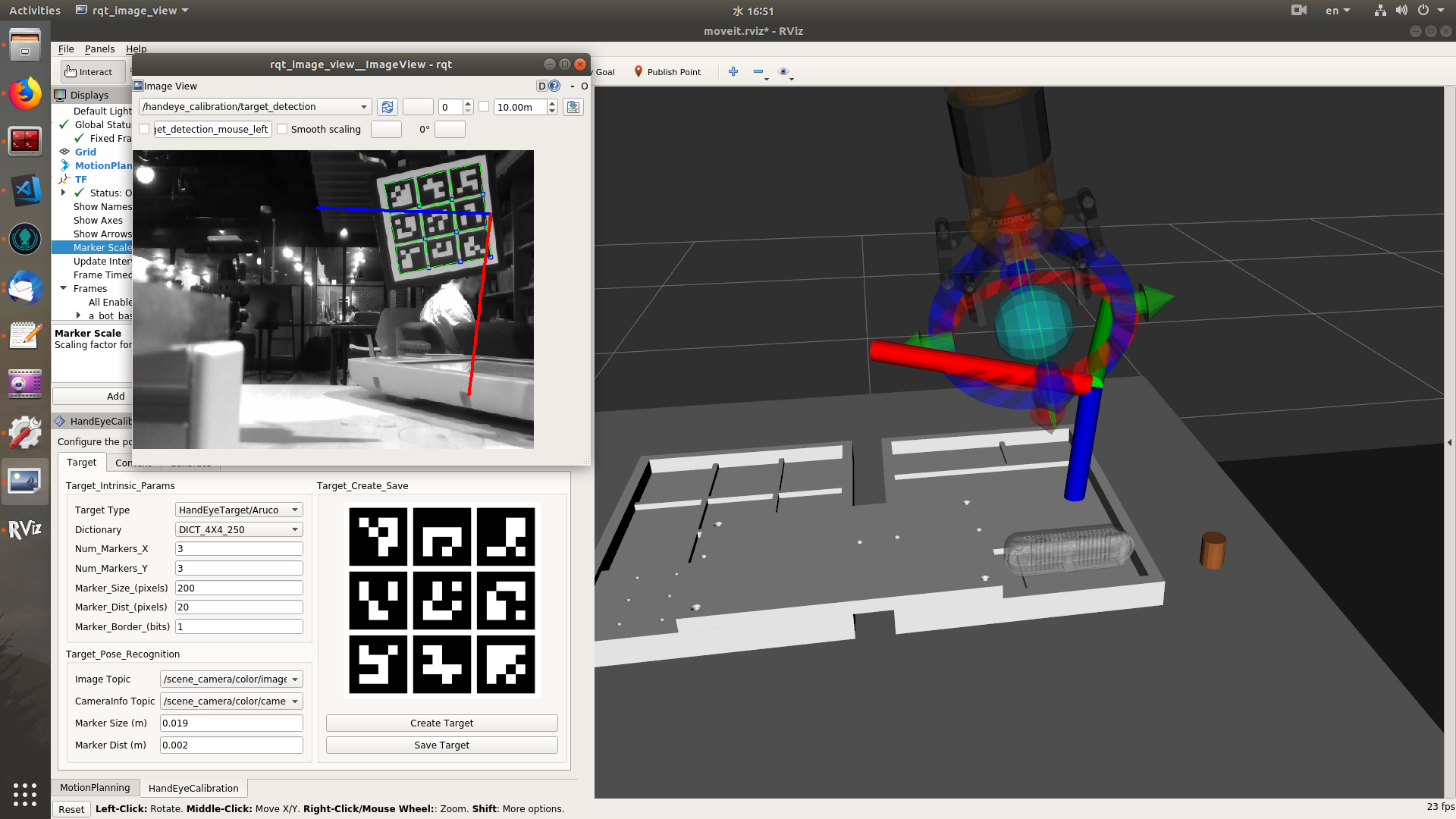
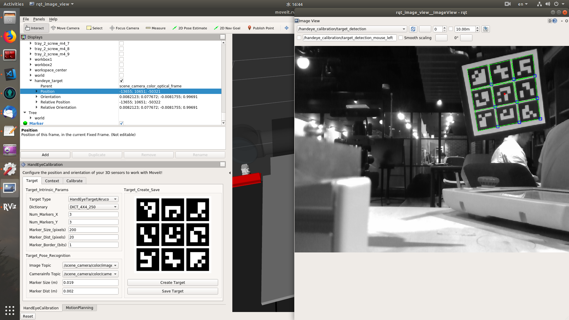
The target tab serves as everything about marker board detection. The target detection plugin publishes the detection result to the "/handeye_calibration/target_detection" topic. The image of this topic contains the original camera image and a coordinate axes painted on the first corner of the marker board. At the same time, the tf of the marker board is continuously updated. The calibration only takes samples of tf transforms, all the pose detection is done in the "target" tab. If the tf frame doesn't exist, the tf look-up will throw exception. User can check if there is a coordinate axes on the image stream of "/handeye_calibration/target_detection" topic. And if he selects the tf frame of the marker board in "Context" tab, he can also check it moving in the FOV of camera.
Currently, user can check the calibration result by checking if the FOV of the camera matches the real scenario, and if the point cloud of robot overlays on the right part of the 3D model of robot. This only provides an approximate check. I haven't implemented covariance estimation, which may provide more information than the intuitive evaluation.
I think there could be a bug here. The list of planning groups are freshed at the init stage of the rviz plugin. So if it is started before a move_group, the list will be empty. I have tested it previously with the moveit config of universal_robot and panda_moveit_config, it can list the arm and gripper groups. Actually, it reads the group names by a planning scene monitor, which listening to the scene topic "move_group/monitored_planning_scene".
I used the maximum value of the progressbar to indicate the total number of joint states, and the current value to indicate the number of completed joint states. When both values are set to zero, i.e. no joint states recorded and no joint states completed, it is moving constantly.
Yes, I haven't put a wait time here. I should do that.
I also struggled here. I have considered to do this fully automatic calibration. Two things changed my mind. I found it could be dangerous for some non-professional users to run the full automatic process if the robot or its ROS driver is not configured properly. And sometimes when a collision happens, it's not easy to stop the robot from the GUI widget if the robot has started moving. If an emergency button is used, that could break the pipeline, and everything may need restart over, except a robust robot ROS driver is used. Another thing is, the plan() of move_group seems need to run in a new thread if it is not run in the main thread, otherwise it will permanently stuck in its callback and cannot return. But if it runs in a new thread, the other operations will also be run in this thread, such as adding samples to the tree view, updating the progressbar and calculating the camera pose. To my experience, this very often brings in some strange segment fault in the qt. Now, the plan() and execute() thread emits a qt signal at its end, and a qt slot is used to deal with the rest operations, that makes it much more robust.
From your feedback, I see that "Calibrate" tag needs to be polished and improved a lot. I agree that it is necessary to split the mixed functions. I will take some time to make the change. |
|
Thanks for the long reply! I can't respond in detail right now, but for now here are some short comments from our experience trying to get it to run today:
Fair enough. I would prefer to save it as an external file, so that one can save a whole calibration procedure for a robot. That seems more logical and modular than saving a whole rviz config. Another problem: when we had the plugin in the rviz config file, the list of Planning Groups would be empty. To get the planning groups to display, we had to restart the plugin, but that resets the parameter values.
What do you mean by "the point cloud"? The topic of the camera, or the topic that is republished by your plugin? Does the plugin publish the initial guess as the position of the camera? We sometimes see our frames in weird places, although they were defined at roughly the correct position in the URDF.
It looks like there is something going wrong in our setup. If you are up for it, we could troubleshoot via Skype. Our time zones are close enough. My handle is the same as here. Other small comments from today:
|
I think it's a bug in my code that the list of planning groups cannot be refreshed when user clicks on it. I will try to fix it. A work-around now can be resuming rviz from the .rviz config file and avoid restarting only the plugin.
"the point cloud" I mean the topic of the camera.
Yes, the plugin publishes the initial guess pose of the camera as a static tf. If the camera pose is defined in a URDF, this tf predefined in URDF will be broken and replaced by the new tf from the plugin.
Yes, I would very much like to help debug the problem. Can you please send me a skype link?
I tested on my side, it happens as you said. I think I must forgot to reset a shared_ptr in the destruction of the "calibrate" tab.
I used the same marker on my side, it works well. I suspect there are two possible reasons for this:
|
|
You can find me on Skype under this link, apparently. edit:
edit2:
|


|
We also found that setting the camera and camera info topics when the marker settings are not yet configured seems to make the marker tracking and detection fail systematically. It might not be updated with new marker settings once it is initialized. This could be the cause behind other bugs, too. |
|
@felixvd Thanks for testing the tool and summarizing the problems. I will try to fix the exposed bugs in this week. I found an answer to one of your questions:
The function drawing the axes in 2D image is actually the |
|
@RoboticsYY As requested in our Skype call, I prepared some sketches of the tabs I would suggest for the plugin. These should replace and add to the current "Calibrate" tab, which is too broad in scope in my opinion:
Would be glad to hear what others think about this. Once again, it's a great effort and we are looking forward to polishing and using it. We managed to calibrate one camera relatively comfortably (except for the bugs). PS: Hope your ROSCon talk got in, mine didn't :I |


|
Also this bag file (link valid for 3 more days I believe) shows the issue we had with the transform being on the wrong side of the camera. |
|
@felixvd Thanks so much for sketching out the tabs. It helped me clear straight on how to split the "calibrate" tab. Great idea for the "test" tab! I never thought about it. I'm still thinking about the recording of joint states and transform samples. Each transform sample usually corresponds to a joint state. Sometimes, when user takes a sample, he may also want to record the joint state. And sometimes, when user wants to remove a sample, this may mean that the corresponding joint state is not good either. Putting the two operations together seems to create confusion, but splitting them apart seems to create some burden of switching between the two tabs. And if not listing the sample and its corresponding joint state together, it's very easy to lose their correspondence, if multiple add/remove operations are done. PS: We are fortunate to hit one short presentation at ROSCon this year. |
|
I think adding a "Record joint state" button to the Collect tab would be perfectly reasonable and solve those concerns. To my mind, the motion to record the samples and the samples that are actually recorded for calibration are separate. I imagine the motion to be set up once and reused often, and the samples to be temporary and discarded after a calibration (which shouldn't take more than 15-30 minutes). I think recording the joint pose and camera image alongside each sample for later inspection would make sense, however. |
|
If this is still happening I will be cheering it on. |
|
This PR has been open for two years, so sorry @RoboticsYY! There has been concerns by @rhaschke and others that these features are a bit too much of scope creep for the core purpose of the MoveIt project (motion planning / manipulation). In addition, we've had lots of infrastructure limitations because of the size of this repo. At this point, I think we should agree on a new repo name for this. We then merge all these PRs there with very little further review, as they've been reviewed and tested a lot already (@jliukkonen @JStech @felixvd ) and this is a new "experimental" feature anyway. That we're excited to use more of! Proposed repo names:
If I get several thumbs up I'll create the repo now. |
|
@davetcoleman Thanks for your continuing support on this topic! I agree that this could be an extra feature that may facilitate the usage of MoveIt in some projects but beyond the core function of Moveit. Looking forward to a new repo for this. I will help addressing the PRs and CI. @felixvd I will continue to improve this tool as we discussed, but I may not be able to make it happen quickly. At the same time, if this tool is interesting to others, I welcome the input of others. |
I guess @RoboticsYY could also create a new repository on their account and transfer ownership to ros-planning once the repo looks good? |
|
To keep things moving, I can make the repo and add @RoboticsYY as admin. Just need someone to weight in on the name. I like the first proposed option. |
|
@felixvd and @v4hn preferred I'll work on getting it further setup.... |
|
@RoboticsYY I'm interested in testing this, can you provide some setup/install directions, how to get the rviz plugin running? I combed through the discussions I can see, and haven't found it yet. Thank you. |
|
@ros-gy To test this tool, you can merge the moveit_calibration PR#4 into the master branch of https://github.com/ros-planning/moveit_calibration. Then use the moveit_calibration PR#5 to install OpenCV 3.4 debian packages. After that, compile the moveit_calibration with moveit on ROS Melodic. The plugin can be loaded from |
|
@RoboticsYY I've attempted using the calibration tool a few times, and could use some explanation on four things, if you don't mind:
-- EDIT -- |
|
I think this issue can be closed. Any further comments or questions should be posted on the MoveIt Calibration repository. |
|
Hi @RoboticsYY I have found this video:
I am involved in the ViSP repository and any information about the benchmark methods would be helpful:
Since ViSP hand-eye calibration method uses a final non-linear refinement stage, I am a little bit surprised to see it performing worse than classical hand-eye calibration methods (Daniilidis method which solves simultaneously the rotation and translation part, and Park, Tsai that solve rotation and translation separately). |

Sorry, But I still cannot find "object frame" in the RVIZ. I think it is also a plugin in Moveit Setup Assistant? Could you please help me? Thank you. @felixvd @RoboticsYY |
|
@ZZWang21 This is a closed issue. I think https://github.com/ros-planning/moveit_calibration repo is a more appropriate position to submit this issue. |
|
no default handeye_target Do I need to find or determine how? |
Hi,
I'm making some effort to add a new screen to the MoveIt Setup Assistant tool for the hand-eye calibration. I would like to get some feedback and suggestions. The reason of why I'm doing this is hand-eye calibration is a key process for the vision-based robot motion planning. If someone want to make a hand-eye calibration, he can find several ROS packages (see list below).
However, not all of these packages has well maintained and detailed tutorials, there is no benchmark tool to evaluate their performance and they are not used straightforwardly with MoveIt. For using one of these packages, one still need much work to understand the working mechanism of the package, set up the specific configuration, prepare the specific calibration board and collect data in a specific way. The result of the calibration is required in running MoveIt for the vision-based motion planning apps.
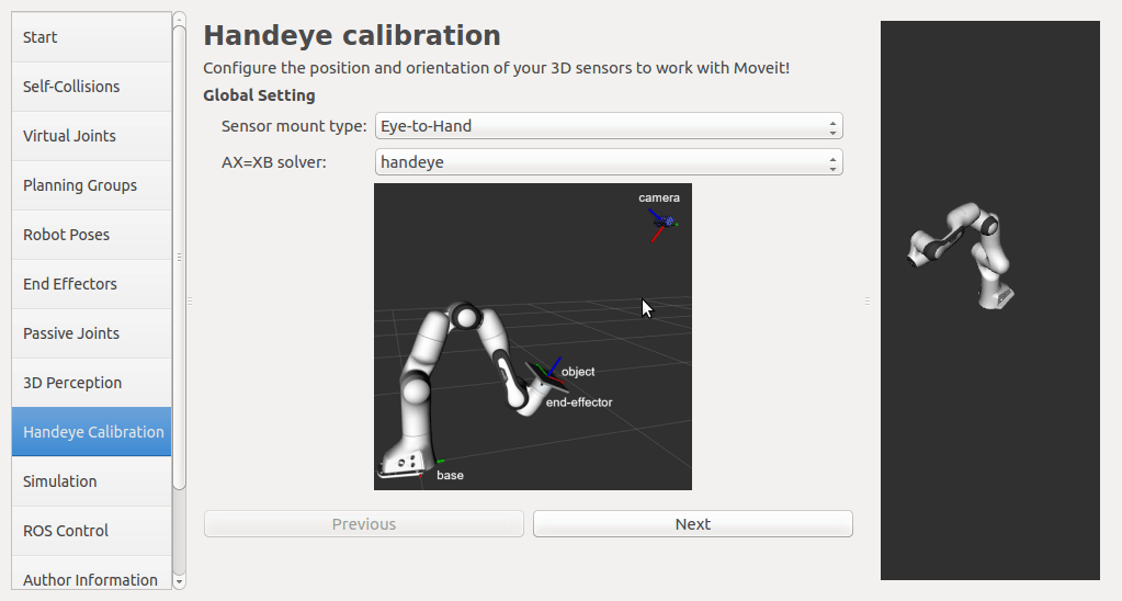
Therefore, I think it is necessary to add a new screen to the Setup Assistant tool for the hand-eye calibration. It would be much convenient for user to set up robot model and camera transform at the same time. Currently, I'm ready to design the hand-eye calibration screen with options below:
from robot-base-frame to robot-end-effector-frameandfrom camera-frame to calibration-board-frame, the hand-eye calibration screen can lookup the TFs of these transforms, so that there is no need to include any specific robot driver or object detection in the screen code. The screen is only used to take snapshots of these transforms.Is there some on-going project for this topic in MoveIt? Or if you have some suggestions, please let me know. Thanks in advance.
The text was updated successfully, but these errors were encountered: