Concept Generation & Selection Document
Robot Soccer | Team Vektor Krum
The goal of this project is to develop an autonomous soccer-playing robot. These robots will compete with each other on a 10 feet by 5 feet field. Both sides of the field will contain goals that are 2 feet wide.
Robot soccer requires true system-level design. Our team must integrate a wireless communication system, computer vision, feedback control, real-time programming, artificial intelligence, and mechanical design. Second, the overall project is much too ambitious for a single student, so teamwork is essential.
The purpose of this document is to outline the process we used to make important design decisions regarding our robots. This document also specifies the facts and the critical assumption we made while creating our design. We incorporated the priorities and specifications we outlined in the Functional Specification Document. For critical design areas like the kicking system and materials, we evaluated several different options, weighed each criteria on it's importance, and compared alternative concepts to a baseline. This document contains the reasoning behind our decisions and explanations of how we made our final design choices.
For each of the critical design areas of our robot, we determined a set of criteria from our functional specifications and customer needs. We used these criteria to weigh various metrics and how well they met our specifications. We then compared several different alternative designs using the same set of criteria. From this data, we generated a scoring matrix to visually show which criteria was used, what baseline was used, and how effective each alternative was. The alternative concept with the highest score based on our criteria was selected and used in our final product.
This section contains both facts and assumptions that were made during the design of our robot.
To compete in BYU's Robot Soccer Competition:
- Build a a competitive, autonomous, soccer-playing robot.
- Develop a computer vision algorithm that takes frames from an overhead camera of the entire playing field and be able to extract important location information.
- Compete on a 10ft x 5ft, walled soccer field.
- Ensure robots fit within an 8"x10" cylinder.
- Design a jersey that jersey specifications and colors. Each robot will be assigned a different color.
- Robots will not observe the off sides rule.
- Robots must be robust. Parts being dropped on the field is a violation.
- Robots cannot damage other robots, the ball, field, or spectators.
- Control the ball without glue, tape or other adhesives.
- Robots cannot hold the ball. 80% of the ball must be visible by the camera.
- Software must be run on Linux install on an ODROID-U3 developer board.
- Computer Vision PCs will communicate to Robots via WiFi.
- No human interaction is allowed after the initial set up.
- Goals will be 2ft wide.
In order to accomplish this we will need subsystems that support the following: Mechanical System:
- Able to move omni-directionally.
- Meet sizing requirements.
- Contain competitive features (e.g., a kicking system) to give an advantage during play.
Motion Control:
- Be able to translate a desired destination and path into accuracy motor motions.
- Interpret the encoders on the RoboClaw to allow precise movements.
- Plan and execute routes quickly.
Computer Vision:
Using the camera feed from the overhead camera, be able to:
- Identify the location and orientation of the enemy team robot.
- Identify the location and orientation of the home team robot.
- Identify the location of the ball.
- Identify the boundaries of the playing field.
- Be able to differentiate between home and away teams.
System Architecture and Artificial Intelligence:
- Be able to intelligently determine the best strategy to take given the score and computer vision data.
- Outperform opponents.
- Use filters to estimate state positions of the field.
- Make decisions very efficiently and quickly.
To aid in our design, we made several assumptions:
- Robots will be allowed to kick the ball so that it becomes airborne.
- We will be provided with the necessary parts and tools to build the robot.
- Batteries are high enough capacity to last the duration of an active game.
- All hardware we are provided is tested an working.
- The $50 of funding we have for the robot will be sufficient to fund the project fully.
- The ODROID-U3 will be able to run Linux and ROS effectively.
- The power provided by the batteries is enough to run all peripheral components as well as the ODROID.
- The sides of the field will be angled so that the ball cannot get stuck against the sides or in a corner.
The design that we propose to use is shown in the block diagram below.
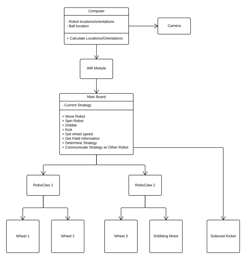
As shown, the camera will be connected to a dedicated PC. This Computer Vision PC will determine the robot locations/orientations and the location of the ball. Then, the Vision PC will transmit this data over WiFi to the ODROID-U3 housed on each robot. The ODROID-U3 will use Robot Operating System (ROS) to communicate between subsystems and make high-level strategic choices. For example, the artificial intelligence will have functions to move, spin, dribble, kick, and pass. It will also have the data and algorithms necessary to determine playing strategies and communicate with the other robot. The main board will then communicate with the motors via UART to the RoboClaw boards. The RoboClaw will then control the actual motors.
We determined that the following three subsystems were critical to the success of the our robots. These were (1) the kicking system, (2) the materials used, and (3) the structure of our artificial intelligence. These are explained below.
The kicking system can provide a significant advantage during play due to the ability to move the ball quickly for passes or shots.
The problem we had to solve with the kicking system was how to power it. We considered several alternatives.
- Pneumatic Kicker
- This option consists of a canister of CO2 and a holding chamber. The holding chamber is filled with air and then quickly released which generates a burst of motion. This pneumatic actuator could be placed behind a kicking bar, allowing a robot to push out a rigid bar to kick.
- Due to how common this option is, we decided to use it as our baseline concept to compare against.
- Spring-based Kicker
- This option would consist of a motor connected to a system of gears that would wind up and latch a spring which could be released to cause a burst of motion. The spring could also be placed behind a rigid kicking bar, allowing the robot to shoot it out to kick.
- Spinning Paddle Kicker
- A motor spins a paddle which would produce the kicking motion when the paddle came in contact with the ball.
- Solenoid-based Kicker
- A solenoid is connected to a kick plate, and when current is supplied the solenoid produces a burst of kicking motion. However, the solenoid will pull, rather than push, requiring us to add an extra lever to convert the pull into a push.
We evaluated each concept against a standard set of criteria. We based the following criteria on our specifications outlined in our Functional Specification Document. We used the pneumatic kicker as a baseline.
-
Accuracy
- How accurate a kicking system when considering it's consistency and how it delivers power in a smooth burst of motion. This criteria was based on the specification that our robot would be able to make a goal from any location on the field with high percentage of success. Higher accuracy is better.
- We weighted this option 30% because it is critical to the effectiveness of our robot.
-
Ball Speed
- This is a measure of how fast the kicker will be able to shoot the ball. The faster the ball can be shot, the less time an opponent will have to react.
- We weighted this option 30% because the speed of a kicker can greatly differentiate us from our competitors and give us a substantial competitive edge.
-
Adjustability
- This is a measure of how easy it is to adjust the speed of the kicker. For example, can the driving mechanism produce both a slow and a fast kick? The more adjustable, the more versatile our robot will be on offense. The more adjustable, the better.
- We weighted this one only 10% because we will generally want to kick at full power. It is more of a convenience than a need that the power can be adjusted.
-
Complexity
- This is a measure of the how complex the mechanical system would be. The less complex, the better.
- We weighted this 20% because it is important that we are able to prototype the system quickly in order to compete.
-
Cost
- In order to minimize the total cost of the project, the less expensive, the better. Thus, a low score represents high cost while a high score on our scale means it was cheap.
- We weighted this only 10% because it will be important enough to the performance of our robot that extra expense is acceptable.

In order to use the pneumatic kicker as a baseline, we set all of its scores a 5 (to set it as the middle point of our 1 to 10 scale).
We then moved on to scoring the spring-based kicker. For accuracy, we gave the spring a 5 because a spring can release a force consistently just like the pneumatic kicker. However, we gave it only a 3 in terms of ball speed because it would be difficult to get a very powerful spring in a small package on our robot. A similarly sized spring will produce much less power than a pneumatic kicker. For adjustability, neither the pneumatic kicker or spring kicker are adjustable. So, we gave the spring a 5. For the spring system, the mechanism to load the spring between kicks would be very complex. The system would involve using a motor and a system of gears to compress the spring until it reached a locking position. Then, another system would be needed to release the lock and allow the spring to decompress. Compared to a pneumatic kicker, this is much more complex and scored a 1. Cost was also scored a 1 because of the amount of extra parts that would need to be purchased.
Next, we scored the spinning paddle kicker. The spinning paddle would operate by having a set of paddles that was constantly spinning. The robot could then turn to hit the ball with the paddles (similar to how a baseball player hits a ball). This scores a 2 on accuracy because it would be very difficult to get consistent shots in terms of both power and angle. In terms of ball speed, we gave the paddles a 2 as well. We would only have room for small motors on our robot, and these motors would not be able to generate enough momentum to create a fast shot. In terms of adjustability, a spinning paddle run on a motor would be extremely adjustable because we could simply change the speed of the motor. Thus, we gave the paddle an 8 on adjustability. In terms of complexity, we gave the paddle a 4 because it would require an extra motor and some simple connects to run. This is slightly more complex than connecting a single pneumatic actuator to a kicking bar. Finally, cost would be slightly higher than the pneumatic kicker because of the extra parts we would need to purchase. Consequently, we gave it a 4 for cost.
Finally, we scored the solenoid-based kicker. In terms of accuracy, a solenoid based kicker would be the most consistent. There would be no loss of power due to lower air pressure or a worn spring. We gave it an 8 for accuracy. In terms of ball speed, a small solenoid can produce much more power than a similarly sized pneumatic actuator, so we gave it an 8. Because we can adjust the current driving the solenoid, we can adjust its power. We gave it an 8 for adjustability. A solenoid is slightly more complex than a pneumatic kicker because solenoid commonly pull rather than push, requiring us to use an extra lever. We scored it a 4. In terms of cost, solenoids are about the same as the pneumatic kicker, so we scored it a 5.
By reviewing each different concept, and evaluating it on our criteria, we determined that the solenoid kicker was the best option with a weighted score of 6.9. We saw value in it's ability to kick is rapid succession, as many times as our battery would allow. The pneumatic kicker would require replacement CO2 cartridges and the spring-based kicker would take time to reload the spring between kicks. A spinning kicker was simply too inconsistent. It was clear that the solenoid-based kicker would be the most effective at helping us reach our desired specifications and metrics.
Another critical design point what centered on what we should build our robot out of. We had to consider many different alternatives. Materials can effect how long the battery lasts, and how agile the robot is. In order to fit our needs, our robot will be made of three layers of hexagons separated by standoffs as shown in the figure below.

We considered several different materials for the body of the robot to make sure it was strong enough to withstand collisions, but cheap and easy to manufacture.
- Acrylic
- This option is a stiff plastic material that can be quickly manufactured with CAD tools and a laser cutter. It is light, but somewhat flexible.
- This has been commonly used in the past. Consequently, we used it as our baseline concept to compare against.
- Aluminum
- This option is a light-weight metal that can be cut with the metal cutter in the shop. It is very rigid.
- Wood
- This option consists of thin wood platforms that can be easily bought and cut. Specifically, we consider the use of composite wood that we have available in our shop.
- K'NEX
- This option consists of plastic K'NEX pieces that connect together forming different shapes. It must be purchased in a K'NEX kit, and pieces may have to be modified to fit our dimension requirements. Because pieces are also able to be disassembled, it is not as robust.
- Weight
- In order to maximize our battery life and aid in agility, the lighter the material of the robot is, the better.
- We weighted this 30% because this characteristic affects several specifications based on customer needs (e.g., both battery life and robot agility).
- Strength
- Our robot must be robust and durable. The stronger the material the better.
- Weighted 20% because we do not want to have a robot break or drop parts on the field (which is a violation). However, because we could rebuild a chassis reasonably quickly, we only weighted this 20%.
- Ease of Construction
- We may need to go several prototypes. We want a material that is quick and easy to cut/construct. Ideally, we can just use a laser cutter. The easier the material is to work with, the better.
- Weighted 30% because we have short deadlines. We need materials that we can manipulate, adjust, cut, or bend quickly so that we can get a working robot structure built as quickly as possible.
- Cost
- In order to minimize the total cost of the project, the less expensive, the better.
- Weighted 20% because we may need to build several robots as we iron our design flaws or discover new ideas. We want each prototype to be as cheap as possible, but this is less important than being able to build it quickly.

For materials, we set acrylic's scores all to 5 to use it as a baseline. Furthermore, during all of our scoring, we assumed that the materials would all be of similar size and thickness to provide a better way to compare them.
First, we scored aluminum. In terms of weight, aluminum of is slightly heavier than the plastic acrylic. We scored it a 4. In terms of strength, aluminum is must more robust and rigid than the slightly flexible acrylic, earning a score of 8. In terms of how easy aluminum is to construct, we cannot use the laser cutter like we could like acrylic. However, our machine shop has a powerful metal cutter that would be easy to use. we scored aluminum a 4 for ease of construction. For cost, aluminum was slightly cheaper than acrylic so we scored it a 6.
Second, we scored wood. There are many types of wood (e.g., balsa, maple, composite, etc.). We only had composite wood available in our shop for comparison. This wood was slightly lighter than acrylic of the same thickness, so we scored it a 6. However, it was also much weaker than acrylic, so we scored the wood a 1 for strength. It would be very easy to accidentally break a platform if a robot hit another robot. As far as ease of construction, our shop's laser cutter is capable of cutting this wood as well, so we scored it a 5 like acrylic. For cost, the composite wood was much cheaper than acrylic, so we scored it a 7.
Finally, we scored the commercially available K'NEX construction pieces. These kits are often used by children to build toy buildings, other tracks. They consist of plastic sticks with various joints for connecting the sticks together. In terms of weight, a K'NEX based robot would be much lighter because of all the hollow spaces in between, scoring an 8. In terms of strength, however, we only scored it a 1. This is because K'NEX are strong in only certain directions. If force is applied against a joint, they can collapse. In terms of ease of construction, we scored it a 3 because it would required time to design and assemble it by hand. We may even need to shorten pieces to ensure that our robot fit the required dimensions. In terms of cost, we would have to buy a commercially available K'NEX kit, which is much more expensive than raw wood or plastic materials, scoring a 3.
Based on the concept evaluation table, we decided to use aluminum to build the body of our robot. We will cut our three hexagonal pieces of aluminum to use as layers, separated by metal standoffs. This will provide us with a rigid structure with plenty of room in the middle to add subcomponents. Although we cannot use the laser cutter, we have access to both aluminum and a metal cutter in our department shop. Aluminum was relatively cheap and also is light enough to meet our specifications.
Once we have a functioning robot, it is crucial to have the artificial intelligence (AI) in place to be competitive.
We considered different strategies for the artificial intelligence of our robots. They range between simple logical commands based only on current robot and ball positions to complex plays that depend on predictions and play state machines.
- Logical
- This option consists of a series of condition statements that determine game state and produce commands. However, it is complex and it is easy to miss cases since nearly every possible situation needs a hard-coded response.
- This is often the first approach that people think of. Consequently, we used it as a baseline concept to compare against.
- Reactive
- This options consists of behaviors that change based on game state. As soon as the game state changes, so does the behavior. That is, no internal state is saved. The robots purely and instantly act based on the positions of the robots and ball.
- Deliberative
- This option consists of a hierarchy of skills and plays that have an internal state and a software hierarchical organization. A deliberative AI can make decisions based on what it wants to accomplish and perform more complex strategies by saving an internal state.
- Hybrid
- This option consists of a mixture of Hybrid and Deliberative strategies. This allows a robot to have a safety net of reactive logic while being able to utilize the organization and internal state.
- Speed of Response
- This is a measure of how quickly our AI can make decisions and respond to changes in strategy. The faster it can respond, the better.
- Weighted 30% because our robot must respond very quickly to an attacking all or an opportunity to score.
- Predictive Capability
- This is a measure of how well the robots can anticipate the future behavior of the ball and other robots. This allows us to anticipate attacks, and better plan offensive strategies. The more predictive capability, the better.
- Weighted 20% because it may only give us an offensive edge. In some occasions, fast reflexes are more important than slower predictive capabilities.
- Modularity
- This is a measure of how modular and easy to change our code is. For example, we want to be able to adjust strategies or tactics easily without having to refactor a large amount of code. The more modular the AI is, the better.
- Weighted 30% because a crucial part of winning the competition will be adjusting to our opponents styles of play. This will require modifications of tactics in code. If the code is modular and easy to update, we will have an advantage.
- Complexity
- To aid in code maintenance and upgrades, the simpler the AI system is the better.
- Weighted 20%. It significantly helps software developers understand and improve code when it's simple. But, simplicity is not as important as functionality.

We used a logical artificial intelligence (AI) approach as our baseline, and set all it's scores to 5.
First, we scored a reactive AI. In terms of speed of response, a reactive AI reacts just as quickly as the logical AI in that it response immediately when any game variables change, scoring a 5. Because no internal state is saved, reactive AI cannot perform any prediction, just like the logical AI. Consequently, we scored it a 5 as well. In terms of modularity, a reactive AI is about the same as a logical AI in that no internal states are saved. In terms of complexity, a reactive AI is much simpler than a logical AI. Rather than trying to consider every possible situation, a reactive AI can act just based on the location of the robots and ball; we scored it an 8.
Second, we scored a deliberative AI. Unlike a reactive AI, a deliberative AI makes decisions on what it wants to accomplish rather than only reactive to the data at a given time. Consequently, its speed of response is slightly slower because it may be trying to meet a goal before changing its course of action, scoring a 3. A deliberative AI is much more dependent on being able to predict the direction of the ball and strategies of the opponents, scoring an 8. In terms of modularity, a deliberative AI software structure is built in a hierarchical, modular fashion, allowing us to modify and tweak tactics easily. For modularity, we scored deliberative AI an 8. For complexity, we gave deliberative AI a 6 because it is slightly less complex than a logical AI.
Finally, we considered a hybrid AI. That is, a combination of reactive and deliberative AI. A hybrid AI is more capable of abandoning a deliberative approach to react to the field situation. Consequently, we gave it a 4. In terms of predictive capability, a hybrid can contain all of the algorithms for prediction that a deliberative AI does, scoring an 8. For modularity, a hybrid can also match the deliberative AI, scoring an 8. In terms of complexity, a hybrid can be a bit less complex than a deliberative AI because it can rely on reactive logic to cover cases that are not accounted for, scoring a 7.
Based on the results of the Concept Evaluation Table, we decided to take a hybrid approach. A hybrid approach combines the best elements from reactive AI and deliberative AI. It shares important modular software organization C++ and makes it easy to modify and add new strategies based on simple tactics. However, it also maintains the quick reactions of reactive AI. With the hierarchical software organization of the deliberate approach, we can choose to be reactive, or easily develop sophisticated offensive strategies. The organization of the hybrid approach will also make testing small code portions easier and result in a more reliable robot. The framework will also be in place that allows us to easily adapt to opponents strategies without having to refactor large amounts of code.
It is crucial that our computer vision algorithm provides the correct data in a timely manner. However, because our vision algorithm is going to run on a powerful desktop computer, we will have plenty of computing resources to do so, even if our algorithm is not maximally efficient.
The only constraint that we need to meet is fitting in the specified robot dimensions. As long as this metric is met, the internal organization of the robot can vary.
Due to the desire to not give any teams an unfair advantage, the hardware we have available to use has largely been standardized. This means that we do not need to consider different onboard computing boards, motors, WiFi adapters, etc. Our priority can shift from hardware selection to getting the most out of the hardware that has been provided.
This Concept Generation & Selection Document has documented the known facts, assumptions that were made, and the resulting decision process used to determine our final design. An explanation of each alternative concept, as well as the motivation behind the evaluation criteria have been outlined. Finally, our final decisions were recorded and justified.