Below is a list of all parts needed to construct your Blot. Keep in mind that the colors shown below are not representative of the actual color of the components. The components are colored differently to ease differentiation when going through these instructions.
| Part | Quantity | Image | Part | Quantity | Image | |
|---|---|---|---|---|---|---|
| M5x35 | 11 | 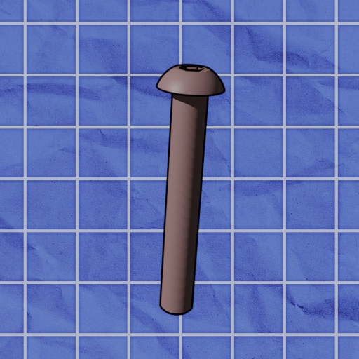 |
M5 nut | 17 | 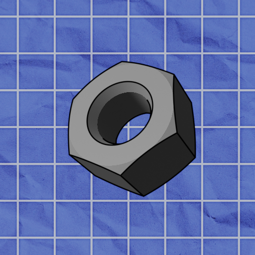 |
|
| M5x20 | 5 | 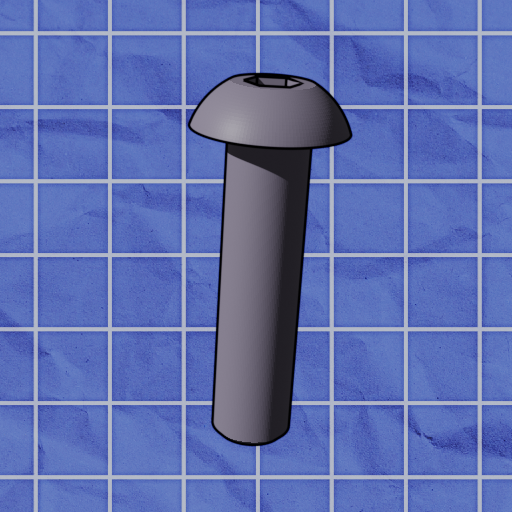 |
M5 T-nut | 13 | 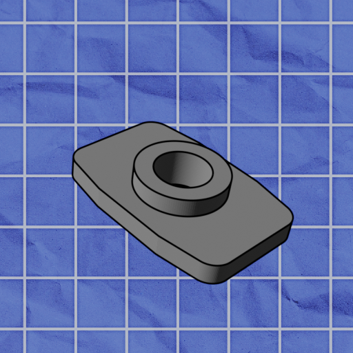 |
|
| M5x20, cyl. head |
1 | 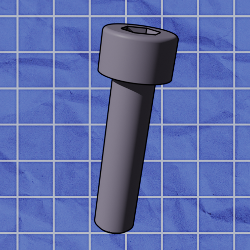 |
Timing Belt Pulley |
2 | 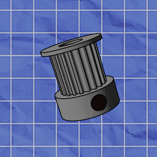 |
|
| M5x10 | 13 | 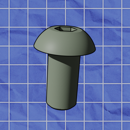 |
Rubber Feet |
4 | 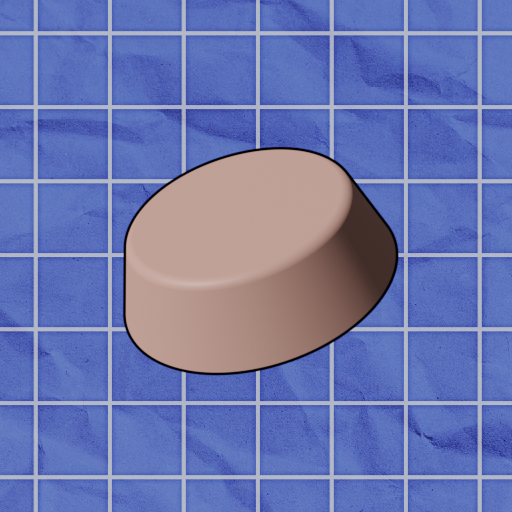 |
|
| M3x10 | 8 | 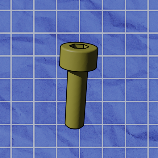 |
Carriage | 1 | 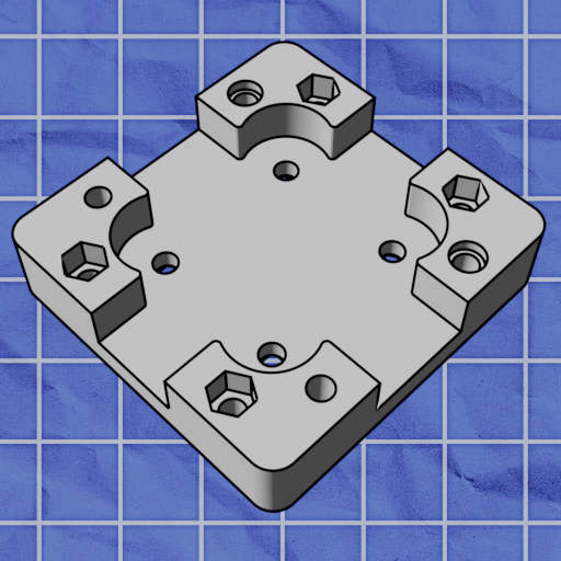 |
|
| Metal Shim (washer) | 5 |  |
Tool Head | 1 | 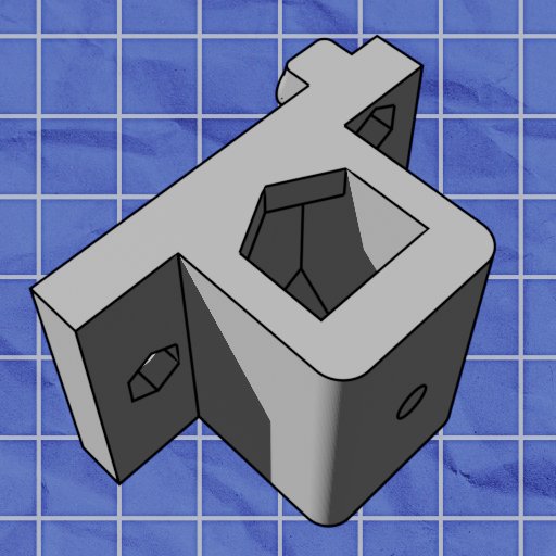 |
|
| Eccentric Spacer |
5 | 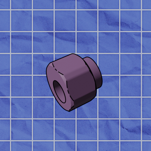 |
Printed Rail | 1 | 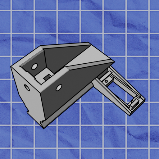 |
|
| Metal Spacer | 4 | 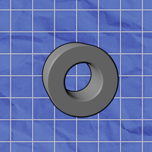 |
Motor Leg | 2 | 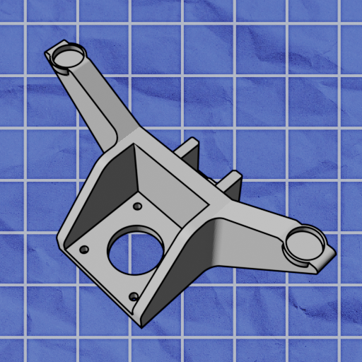 |
|
| V-Wheel | 11 | 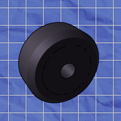 |
Belt Clip | 1 | 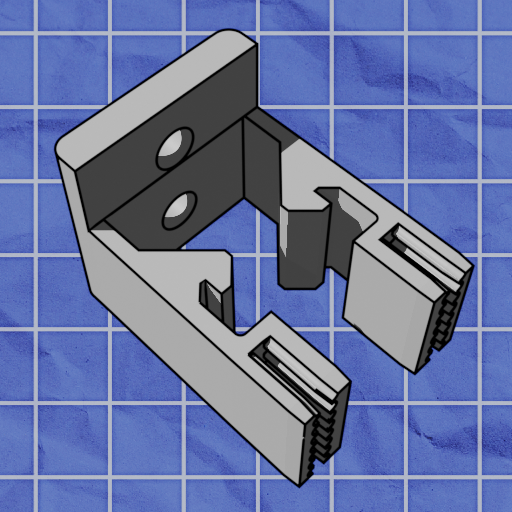 |
|
| Flanged bearing | 10 | 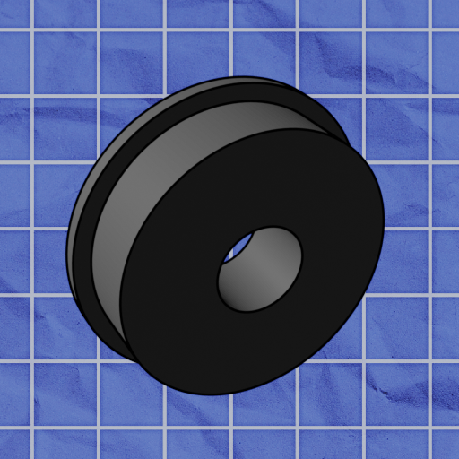 |
PCB Mount | 1 | 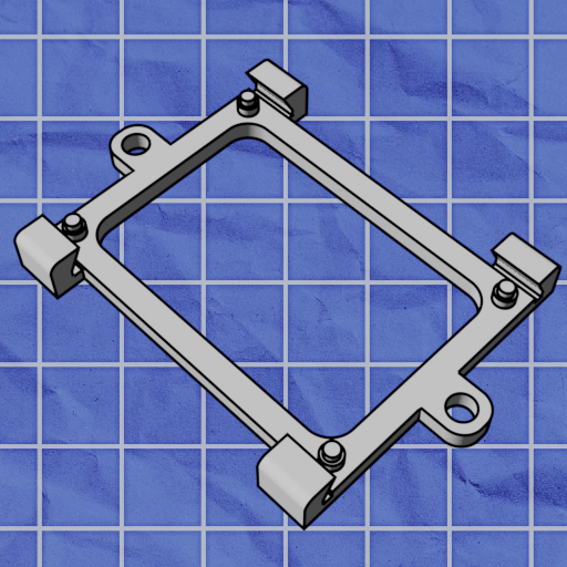 |
|
| 2020x250mm Aluminum Extrusion | 2 | 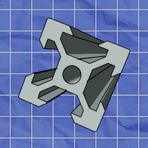 |
Stepper Motor |
2 | 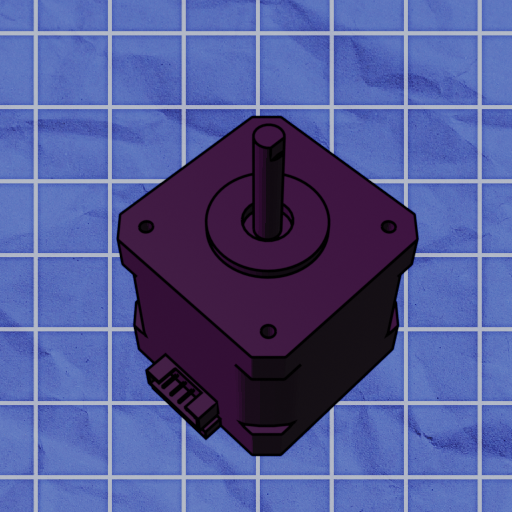 |
|
| PCB | 1 | 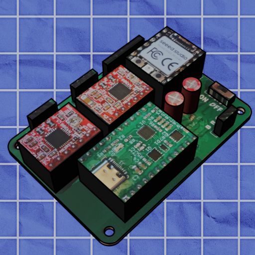 |
Servo | 1 | 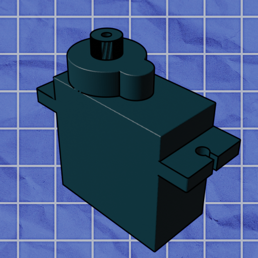 |
|
| Carriage Plate | 1 | 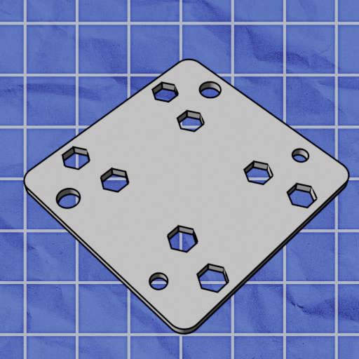 |
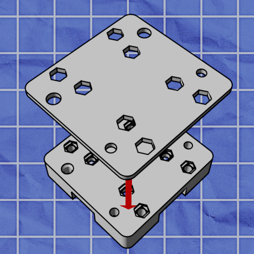
Align the aluminum plate with the bottom of the carriage. the holes in the alumnium plate will only properly align with the holes of the bottom of the carriage in one direction.
Insert 4 nuts into the nut traps on the back of the carriage. Nut traps are hexagonal holes which nuts fit into.
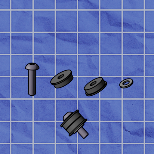
Next, create 4 belt bearing assemblies in the manner shown above using M5x20mm screws, 2 Idler bearings, and shims.
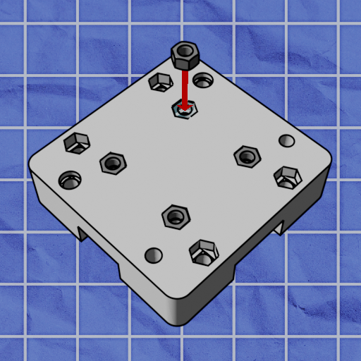
Flip over the carriage, and install your bearing assemblies into the carriage.
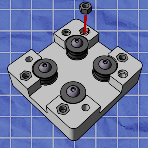
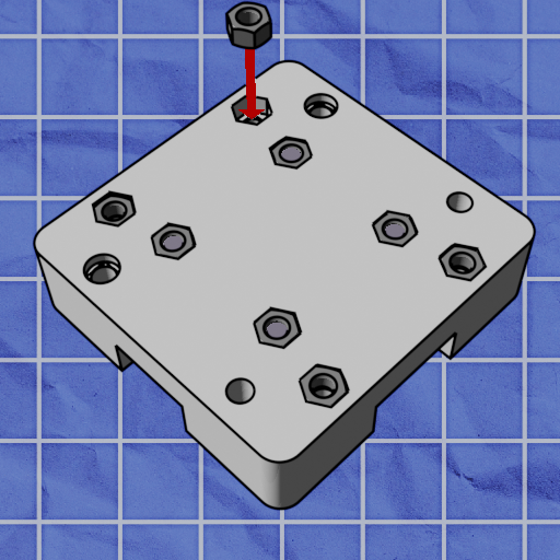
Insert 8 nuts into the remaining nut traps before proceeding to the next step.
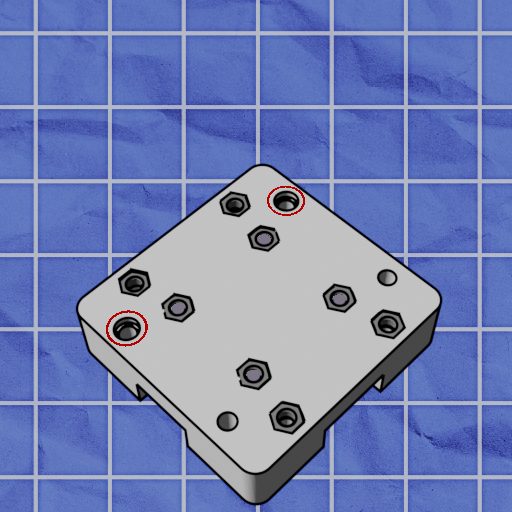
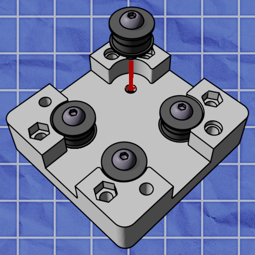
On the back of the carriage, 4 circular holes can be found. Two of these holes are large, and two are smaller. Identify the two large circular holes, circled above.
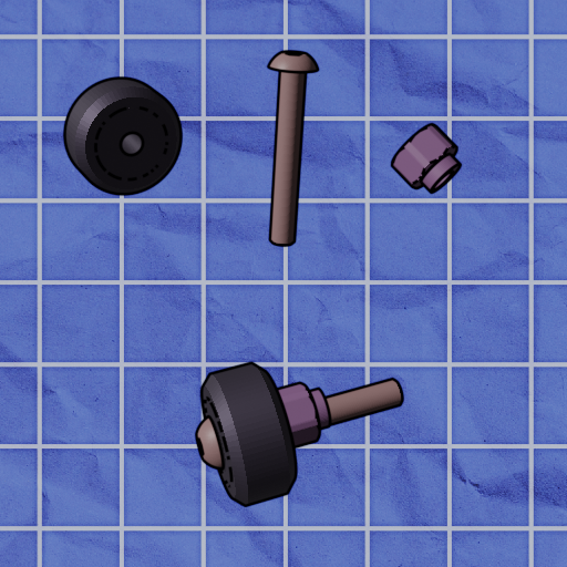
Assemble 2 V-wheel assemblies as shown above using V-wheels, m5x35 screws, and eccentric spacers.
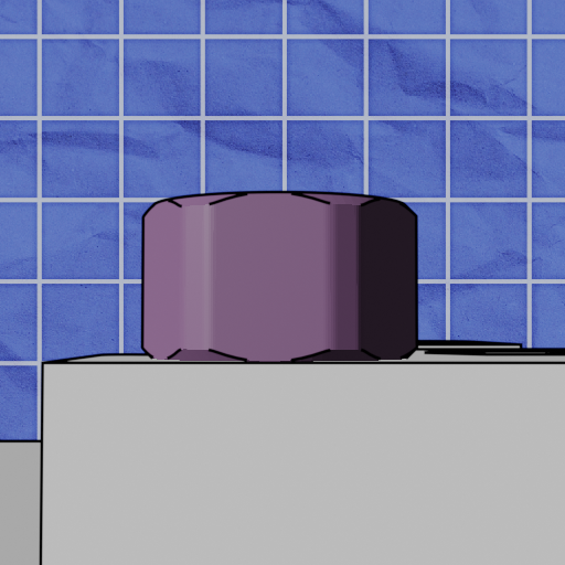
Screw these assemblies into the large circular holes identified earlier. Ensure that the eccentric spacers are flush with the part they're screwed into, as shown above.
Next, assemble 2 V-wheel assemblies as shown above using V-wheels, m5x35 screws, and spacers. Do not use eccentric spacers in these assemblies.
Screw in these two V-wheel assemblies into the remaining two circular holes. We will now repeat this process for the other side.
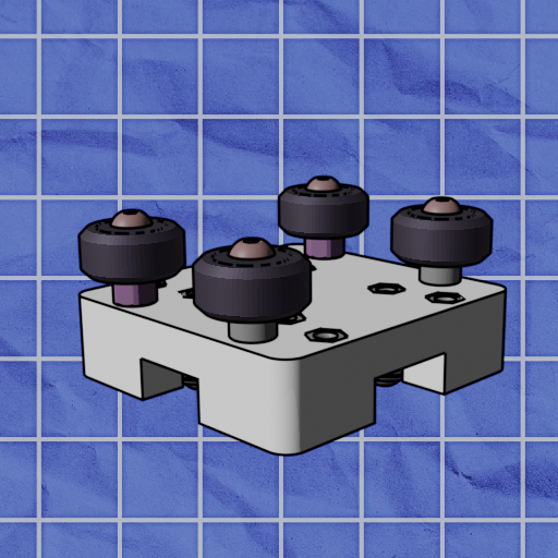
Flip over the carriage, and identify the larger set of circular holes as shown above.
Assemble 2 V-wheel assemblies as shown above using V-wheels, m5x35 screws, and eccentric spacers.
NOTE: If the washer(little bronze ring) in the V-wheel looks misaligned(see image), use an allen key to re-align it.

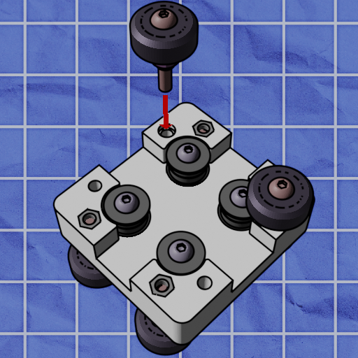
Screw these assemblies into the large circular holes identified earlier.
Next, assemble 2 V-wheel assemblies as shown above using V-wheels, m5x35 screws, and spacers. Do not use eccentric spacers in these assemblies.
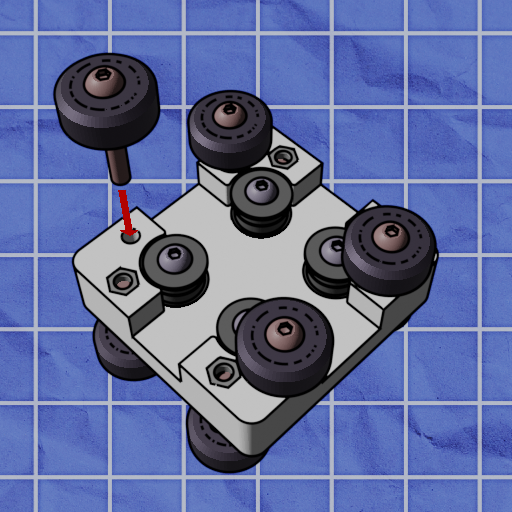
Screw in these two V-wheel assemblies into the remaining two circular holes.
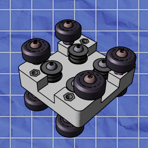
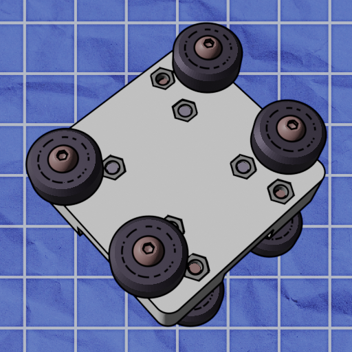
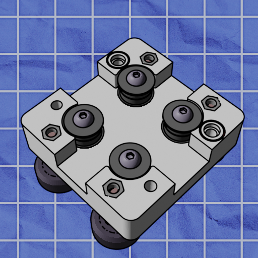
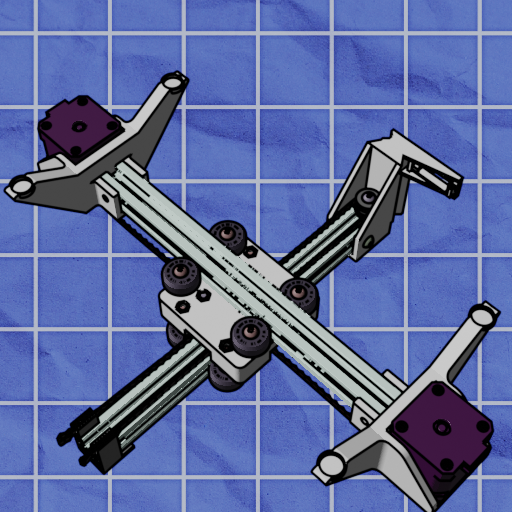
Your final carriage assembly should now look like this.
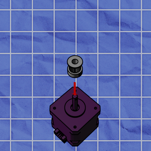
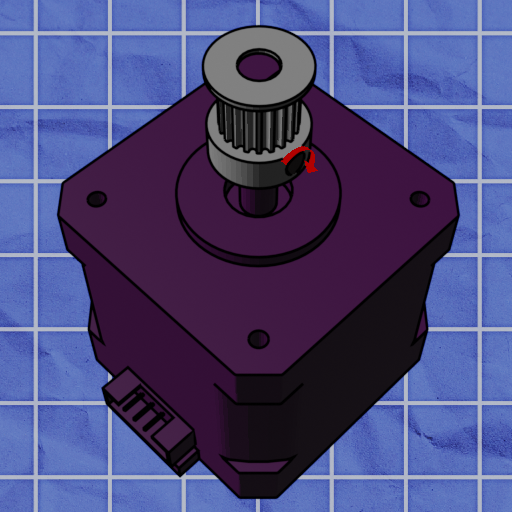
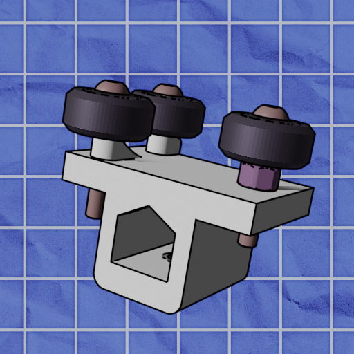
Insert a timing belt pulley onto a stepper motor, and tighten the collar screw so that the pulley is flush with the motor shaft.
Insert a motor into the motor mount, with its cable facing away from the legs, as identified above. Ensure that the shaft of the motor is going through the large circular hole in the center of the motor mount.
Screw the motor in place with 4 m3x10 screws. Do this assembly twice, once for each leg.
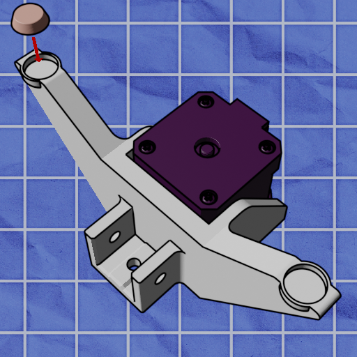
Attach rubber feet to the bottom of the legs.
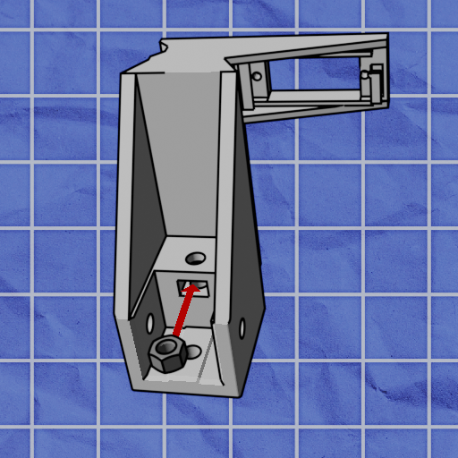
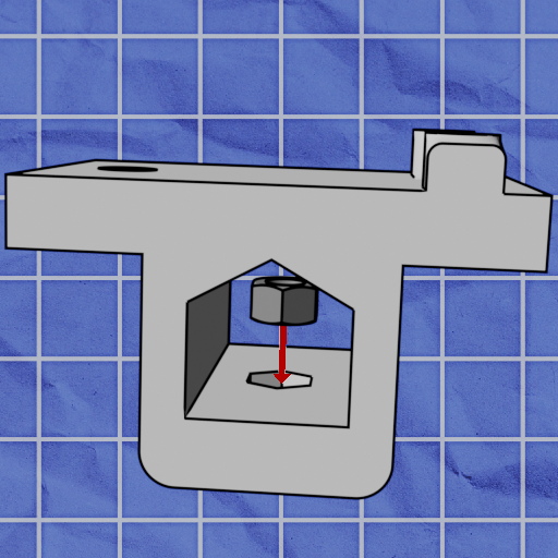
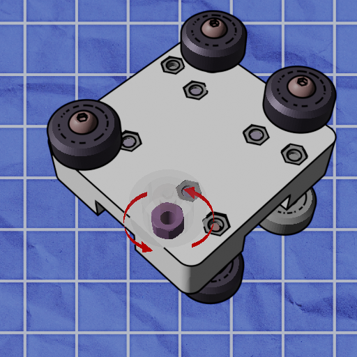
Insert a nut into the nut trap as identified above.
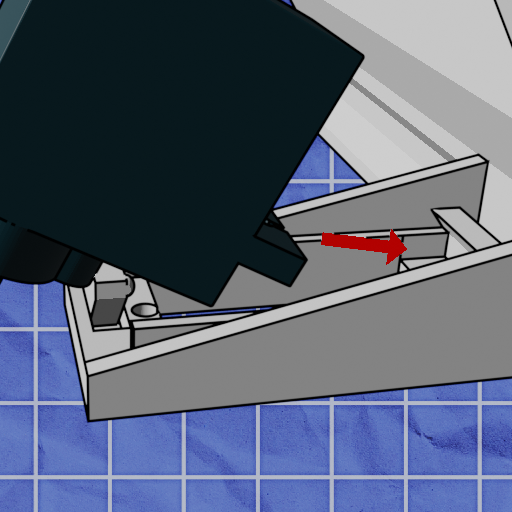
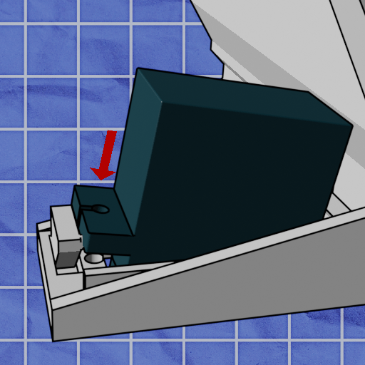
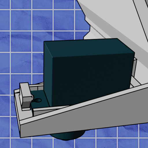
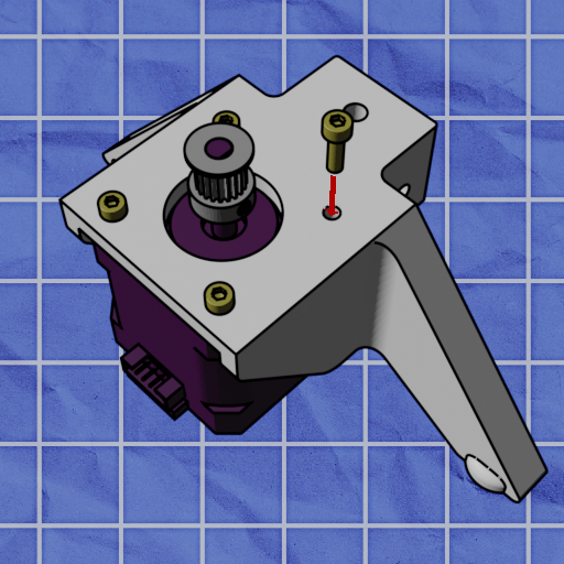
Insert the servo in the orientation shown above. The servo wire should be facing away from the printed rail.
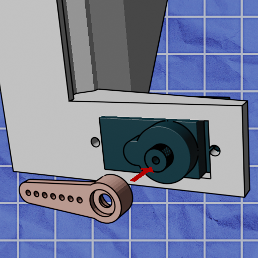
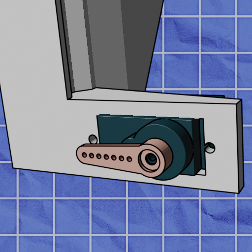
Attach the servo arm, facing to the left. Make sure to place the servo arm on at the angle shown above (do not place it at the wrong angle, and then proceed to rotate the servo).
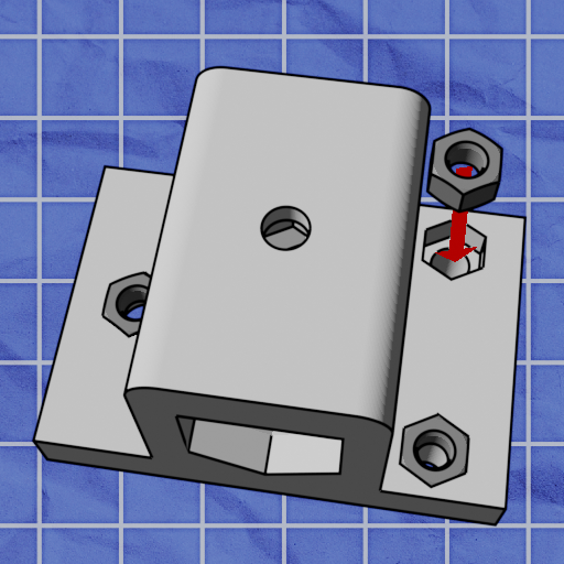
Insert 4 nuts into each of the nut traps.
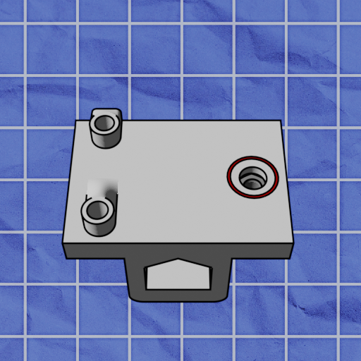
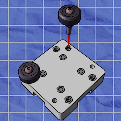
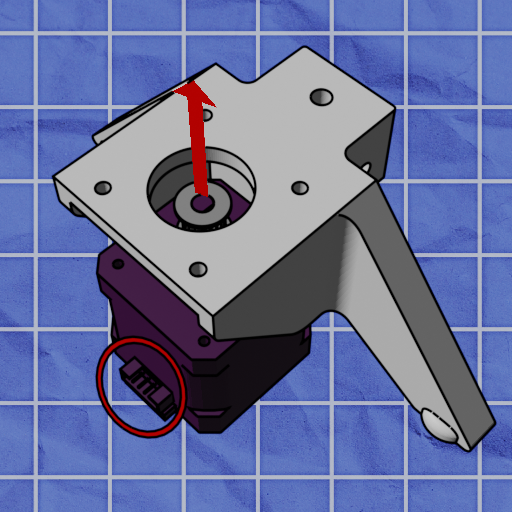
Identify the large hole on the back of the tool head.
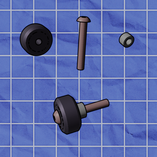
Assemble a V-wheel assembly as shown above using a V-wheel, m5x35 screw, and an eccentric spacer.
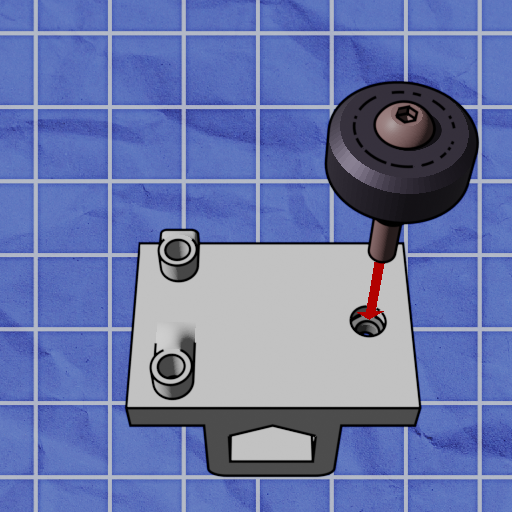
Insert the V-wheel assembly into the hole previously identified and screw it in.
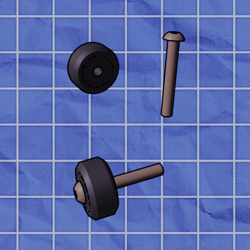
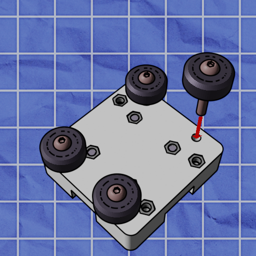
Assemble 2 V-wheel assemblies as shown above using V-wheels and m5x35 screws.
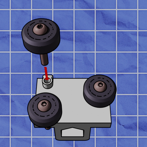
Screw the two assemblies you just assembled into the remaining two holes on the back of the tool head.
Your final toolhead assembly should now look like this.
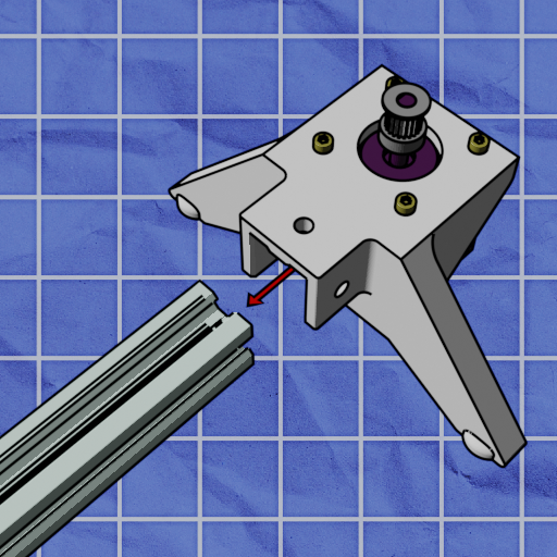
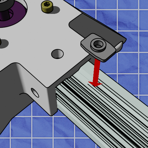
Insert one aluminum extrusion into one of your leg assemblies. Be careful as it may require some force.
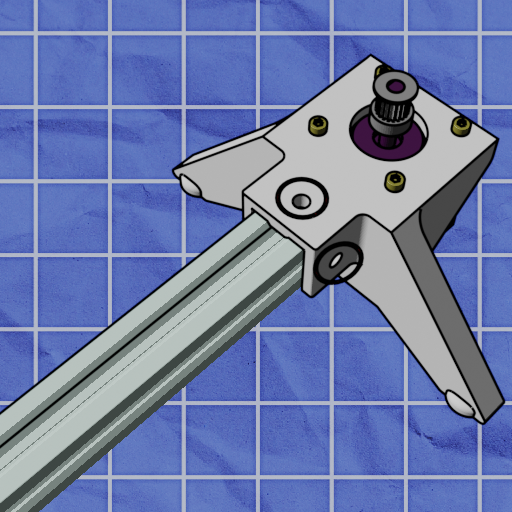
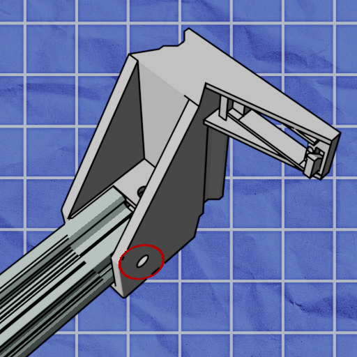
Identify all three circular mounting holes on the end of the leg.
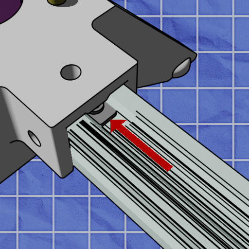
Insert a t-nut into the rail, and slide it under one of the circular holes on the leg, so that the hole of the t-nut and the hole of the leg line up.
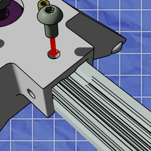
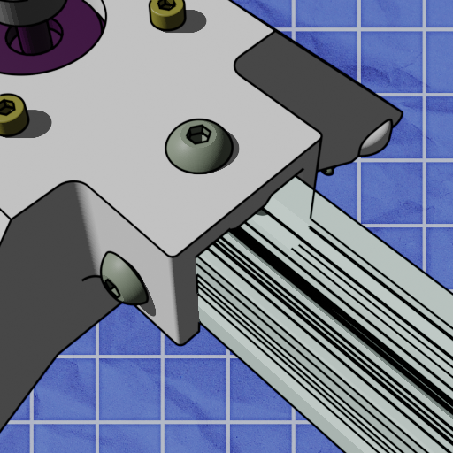
Screw the leg to the rail using M5x10mm screws. Repeat this for all three holes previously identified.
Attach the carriage onto the rail with the belt bearings facing upwards. Should this prove difficult, you may need to adjust the eccentric spacers using the 8mm wrench provided. turning the eccentric spacers changes the width of the space between the v-wheels.
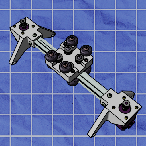
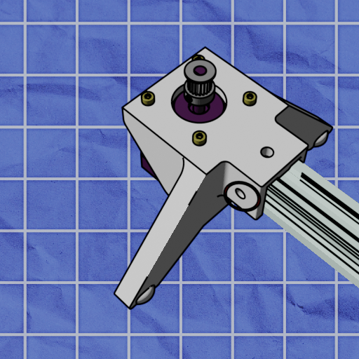
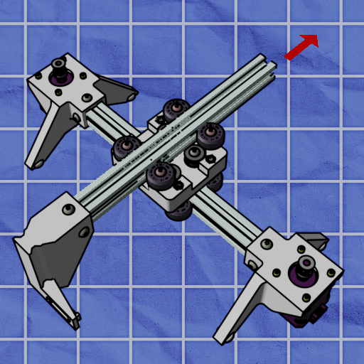
attach the other leg, enclosing the carriage between both legs. Be careful as it may require some force.
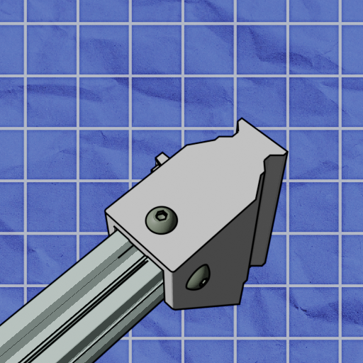
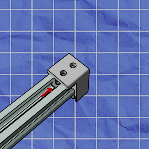
Attach the printed rail to one side of the other aluminum extrusion. Be careful as it may require some force.

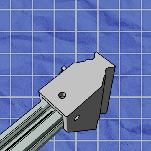
Indentify all three circular mounting holes on the printed rail.
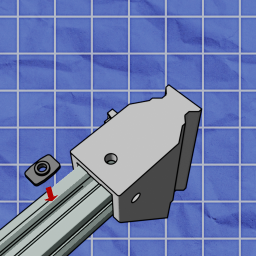
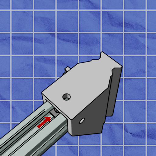
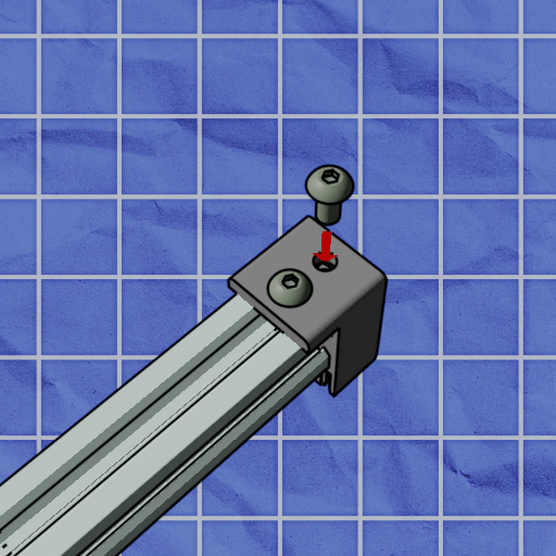
Insert a t-nut into the rail, and slide it under one of the circular holes on the leg, so that the hole of the t-nut and the hole of the leg line up.
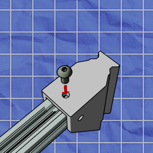
Screw the leg to the rail using M5x10mm screws. Repeat this for all three holes previously identified.
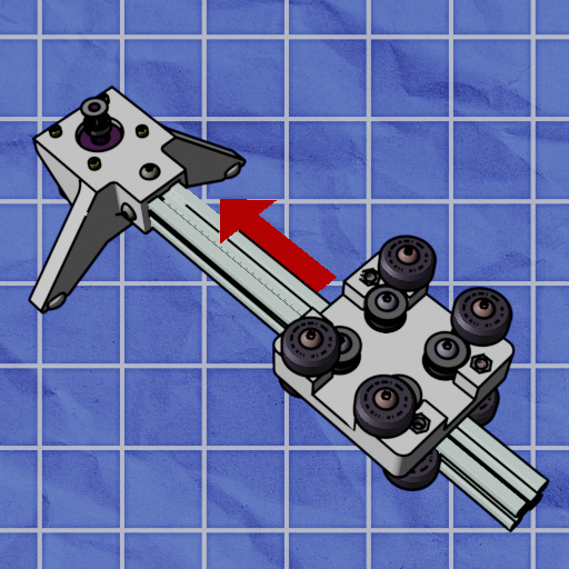
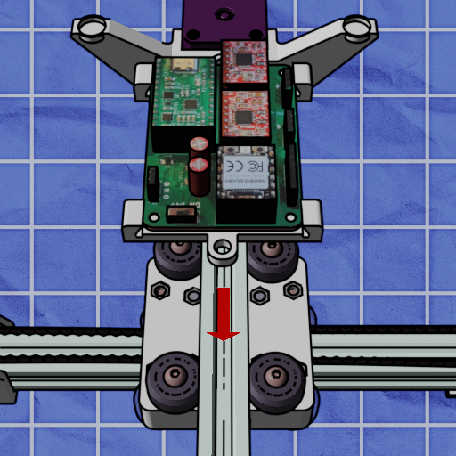
Insert the rail into the top of the carriage. Then, flip the blot over so that its feet are facing up.
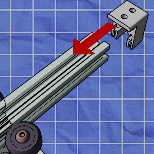
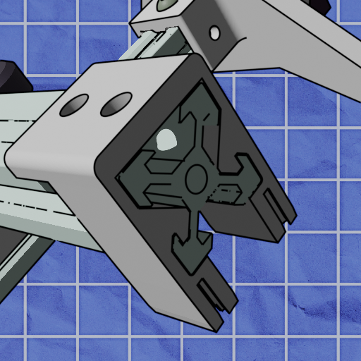
Next, we need to attach the belt clip. Make sure it is flush with the aluminum extrusion. *Be careful as it may require some force.*
Screw it on using the same t-nut technique.
Create another belt bearing assembly and ensure the belt is behind it.
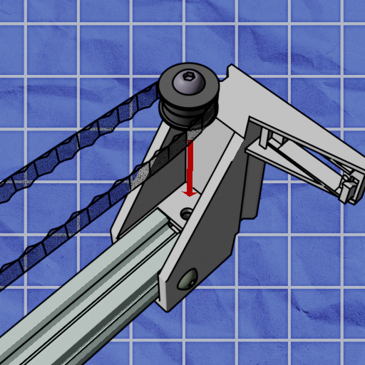
screw it into the printed rail.
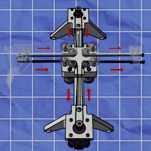
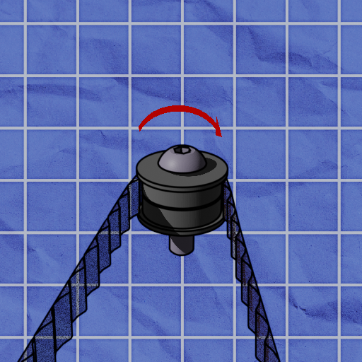
Here comes the hardest part: routing the belt. Ensure it goes around the shafts of both motors, and runs between the belt bearings within the carriage.
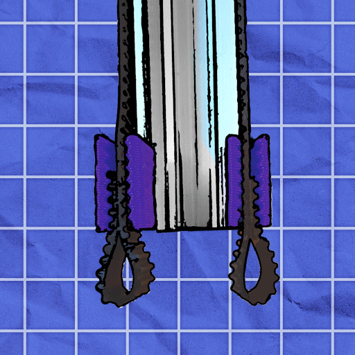
At the belt clip, bend the belt around on itself (with the teeth facing outwards) in order to hold it tight.
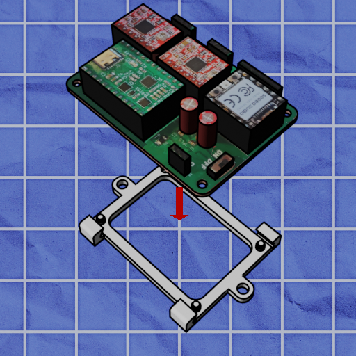
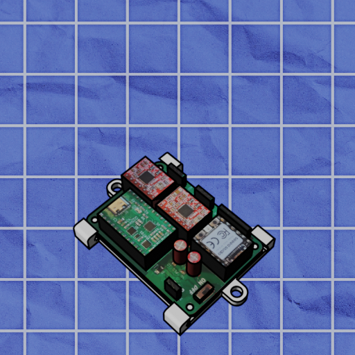
Attach the pcb to its mount. Ensure all corners are clipped on.
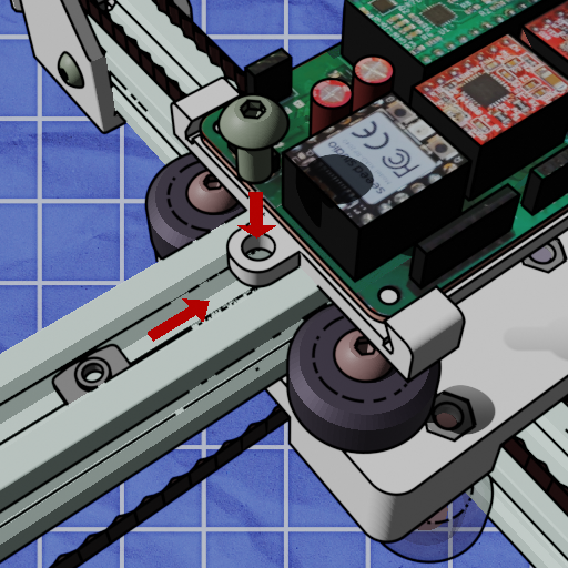
Finally, Screw the mount onto the lower rail using m5x10mm screws and t-nuts.
Now that you have an assembled blot the next step is to do first-time tuning. You'll probably only have to do this right after assembly and every once-and-a-while (ie. if you pack your blot in a suitcase and take it to a hackathon).
Follow the Tuning guide to get started.