Fabrication v2 #1616
Replies: 15 comments 46 replies
-
|
Ambitious! Don’t think there’s anything on the list that I dislike. |
Beta Was this translation helpful? Give feedback.
-
|
Most of the backend is already done, so this will mostly be just making a really good GUI. |
Beta Was this translation helpful? Give feedback.
-
I see an another option: surface limit. If you insert an IC inside of IC, it acts just like you had copy-pasted all the internal components, and occupies same space. This way nested IC's can be seen as some kind of modularization. This can be further extended to some kind of reusable blocks. You can create a sub-blueprint inside, make changes to it and all these changes will be automatically synchronized to all instances of that blueprint. So you will not have to copy-paste all your 16-bit register every time you make a change to a single bit. |
Beta Was this translation helpful? Give feedback.
-
But the whole idea was to transition from artifical counts to natural limitations.
This is the whole point. You can't squash 32x32 to 1x1.
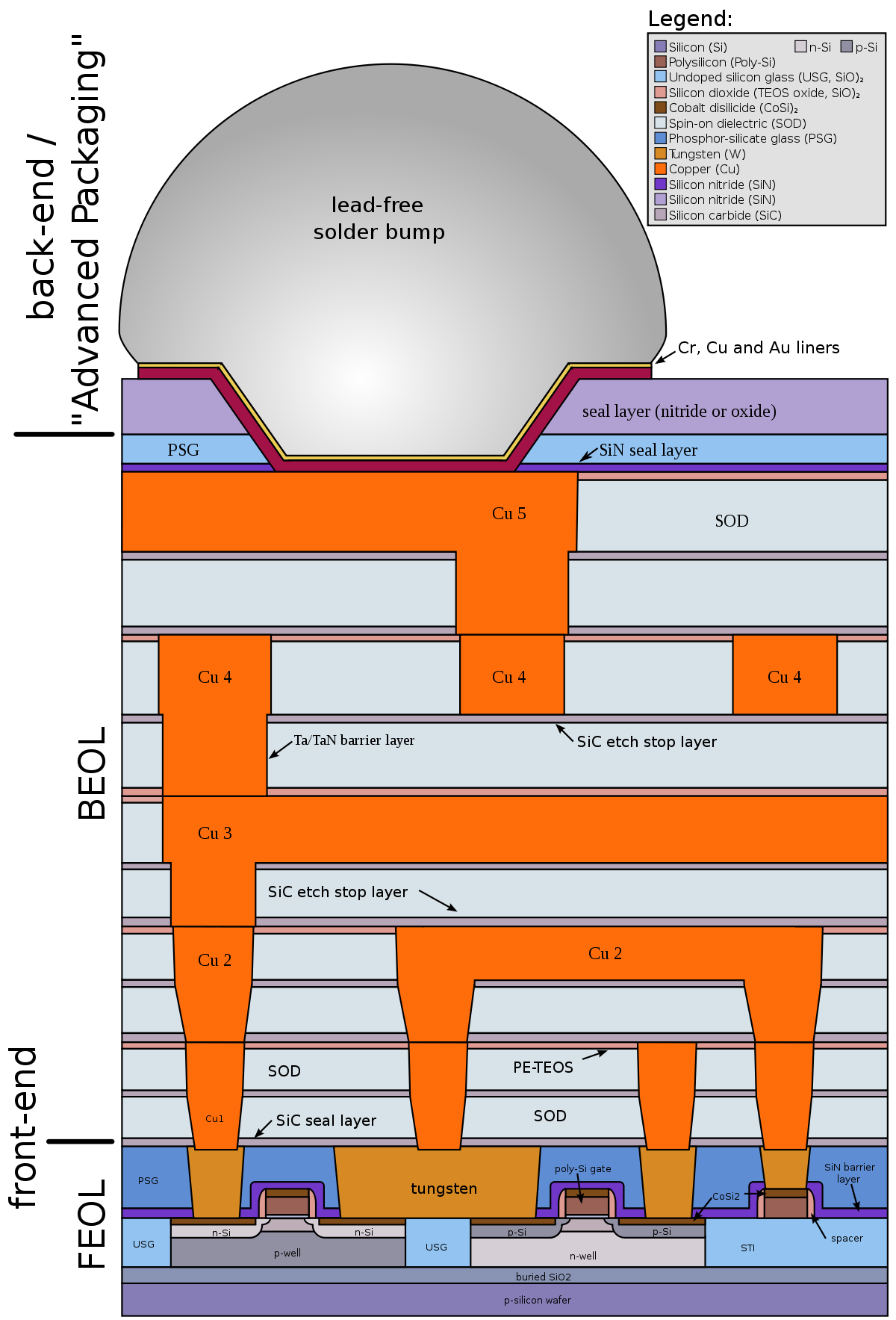
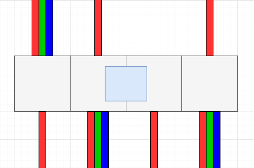
This is exactly how integrated circuits work, with exception of recent 3D circuits. 3D circuit is like a stack of basic circuits, and basic circuits are like this:
|
Beta Was this translation helpful? Give feedback.
-
I don't really care about the wires that much, the main thing is to limit gates. Wires don't effect performance at all when the gate is actually running. Actually, they are removed altogether by the compiler. This is just an alternative to making wires 'free'.
While I don't mind going for realism, limiting gates to a single layer seems a bit too restrictive. |
Beta Was this translation helpful? Give feedback.
-
|
I don't think that it's restrictive. Not only because realism.
|
Beta Was this translation helpful? Give feedback.
-
|
With respect to limited space, is it worth mentioning that, if we care anything about realism, you could fit a LOT of gates into a square-metre IC in real life? |
Beta Was this translation helpful? Give feedback.
-
Not a lot of already-square-metre gates. But yes, maybe something like 128x128 is feasible. |
Beta Was this translation helpful? Give feedback.
-
|
Also there is some kind of inconvenience that you are limited to 64 connections to the outer world. What do you think about multi-block IC's?
|
Beta Was this translation helpful? Give feedback.
-
One way is to divide larger (32x32, 64x64) blueprints to 16-block "cells", with each cell targeting specific part of multi-block circuit. Multiblock circuits, however, imply that no IOs can be placed on sides, only on top/bottom. |
Beta Was this translation helpful? Give feedback.
-
eh? I don't see why that would imply that. you just can't get as much side-io for a 2x1, but then you pull out a 2x2 and you're back yo having the same number of possible io on each side? |
Beta Was this translation helpful? Give feedback.
-
|
Yeah, sorry, "horizontal multiblocks" imply. Of course, multiblocks can be of arbitrary shape. |
Beta Was this translation helpful? Give feedback.
-
|
what is the point of having more IO if you have less circuit space ? |
Beta Was this translation helpful? Give feedback.
-
|
i think the proposal is that you essentially get more circuit space as the IC takes up more blocks. i.e. a 2x2 block IC gets 2x2 cells worth of space, where each cell is a 16x16, 32x32, 64x64 (potentially depending on progression or similar? i'm basically thinking of the larger cell sizes as smaller manufacturing processes, i.e. 100nm vs 50nm vs 17nm) does that make sense? |
Beta Was this translation helpful? Give feedback.
-
|
And third point: in old fabrication implementation, I often encountered designs that worked in simulation, but refused to work after being fabricated. So I think that special care must be taken to make simulation code as closely resemble real-world behavior as possible. With all bugs faithfully reproduced :) |
Beta Was this translation helpful? Give feedback.
-
Cells are initially designed to make look-up tables, and they do it excellently. Crossing two wires with a null cell is rather a side-effect. So cells will be appreciated even in multi-layered IC's. |
Beta Was this translation helpful? Give feedback.
-
|
Are the three that I mentioned good enough (Wire over wire, bundled over bundled, and wire over bundled)? There can be right angled variants too but i'd really rather not go that crazy with the cells. |
Beta Was this translation helpful? Give feedback.
-
|
LUTs usually use nulls, buffers and inverters |
Beta Was this translation helpful? Give feedback.
-
|
personally, i'm okay with luts being a bit more complicated if we have additional layers. It's a trade-off, for sure, and I'd definitely want to play with it a bit before calling it "good", but between nested ICs and extra layers I don't see it being that bad. |
Beta Was this translation helpful? Give feedback.
-
|
I can make this work. I'll implement null, buffer, and invert cells. |
Beta Was this translation helpful? Give feedback.
-
|
PNG export would be appreciated, even if it's not useful, as it could be used as a preview image for a shared blueprint that you can view before pulling in the actual blueprint string. With some clever tricks you could probably even encode the blueprint string into the PNG, but such tricks tend to break when sites re-encode the image, so it's probably not worth it. at least we could probably be more reliable than PNG-ZIP polyglots... |
Beta Was this translation helpful? Give feedback.
-
|
If its just for the purpose of viewing in-game before, importing from a string or url, it can just be rendered straight from the string. Could be a feature of the blueprint sharing block itself. That doesn't require the ability to actually export png files. However, if you want to be able to create some kind of external website or gallery of blueprints, i suppose they can be useful. |
Beta Was this translation helpful? Give feedback.
-
|
That's exactly what I was thinking about: sharing the blueprint on some external site (say, twitter, or some random forums) and being able to view the preview without having to open up the game at all. alternatively, could be able to do something with a website that generates the preview image in the browser (with wasm via JWebAssembly or similar for code reuse? idk.) and then the canonical blueprint string format could be a link to said website, with all information encoded in the URL. |
Beta Was this translation helpful? Give feedback.
-
|
This is not meant as a strong request, just something to consider—you may consider that it’s OP, but here goes. Analogue I/O for bundled cable. Obviously in the one-hot encoding you’ve been using for analogue I/O, a full bundled cable would require a very large IC (a side length of 256), but a more compact analogue encoding (binary?) could reduce that to something a bit more practical. Even sticking to the one-hot encoding, being able to handle a handful of analogue signals in a cable—maybe three or four—might be quite useful in some situations. |
Beta Was this translation helpful? Give feedback.
-
|
Hmm. That seems way overkill, but technically there is no limitation that would prevent this from working. The most obvious thing I can think of is, using 16 different coloured bundled IO tiles, each using the one-hot mapping. (i.e. the white bundled IO maps external analog white, etc.) |
Beta Was this translation helpful? Give feedback.
-
|
Yeah, it’s something that could be useful any time you have multiple analogue outputs from an IC. As it stands today, you have to take up a bunch of extra space outside the IC to bring the analogue signals into coloured wires and then collect the coloured wires into a bundle—and if you need more analogue signals than you can fit on four sides, you have to do some inter-IC communication. Being able to run the bundled cable straight into the IC but still deal with analogue levels would make that sort of thing much more compact. |
Beta Was this translation helpful? Give feedback.
-
|
This isn't a way to 'deal with' analog signals inside the IC. There is no analog in there. Wires don't actually have a strength that drops over distance. It's all digital. You can do something to map analog into colours or whatever, but within the IC, there is no analog. |
Beta Was this translation helpful? Give feedback.
-
|
I know. But external devices use analogue levels, so if an IC is trying to, say, control an external system that comprises four separate machines each with an analogue input, then it would be useful if it could output four analogue levels into four colours of a bundled cable, which could then be broken out and delivered to the four machines. This is entirely about the external side—what the analogue signals map to on the inside of the IC is something I haven’t thought about much, just that it would be useful to have some way to accomplish this, and today there isn’t (you can only have bundled or analogue on a side, not both). |
Beta Was this translation helpful? Give feedback.
-
|
That makes sense to me. I'll add this to the list of connection types above. |
Beta Was this translation helpful? Give feedback.
-
|
Will the layer size maximum could be increased ? the 64 limit is a bit too small for some of my ICs. I think that (#1616 (comment)) is a good idea, because of the 4input/output limit, for example, i have a latch matrix, with 7rows and 5columns, represented by bundled inputs on right and down, but i have data out at left and data in at top, but i would need write enable signal input, but there is no room for it so i have to use the right bundled input black colour input to make it work, but my issue is that with the new features i'll be able to put more rows/columns, the idea is that i would have 8rows and 8columns, but then i won't have any room for the write enable. If the null gate could still be a thing that would be very nice, so we don't have to use other layers just to jump wires, that way it doesn't disturb other circuits on other layers. |
Beta Was this translation helpful? Give feedback.
-
How delay gates are represented with this low-level bytecode? E.g. 8 tick delay, or even 256 tick. |
Beta Was this translation helpful? Give feedback.
-
|
Delays work because there is an additional register that contains world ticks. Timing-based logic will use a combination of time register and some of its own to determine when the signal came in, and how long it has to wait before it writes to the output. Also it's not compiled to pure byte code (yet). Example, a simple repeater that delays 2 ticks will read from:
And will write to:
A very simple state machine can be implemented with these: https://github.com/MrTJP/ProjectRed/blob/main/src/mrtjp/projectred/fabrication/gatetile_seq.scala#L326 |
Beta Was this translation helpful? Give feedback.
-
|
Here’s another request: relaxation of mixed input/output requirements for analogue and bundled I/O. Right now, you get an I/O direction conflict error if you try to have some colours inside a bundle as inputs and some as outputs on the same side, or a mix of inputs and outputs for analogue signal levels on the same side. For bundled cable, I think the use cases are pretty obvious—the same bundle can use different wires for sending signals in different directions. For analogue levels, I also have a use case in mind, although a more rare one: illumar feedback buttons. I thought it would be neat to have a light-up power button that can be pressed to turn a machine on and off, and also shows the current state of the machine (on or off) by glowing or not. The problem is how to detect the button being pressed when it’s also powered in order to glow. With analogue I/O, this is achievable: the button sends out a level-15 signal when pushed, but glows when any nonzero signal reaches it. So, when the machine is on, you can make the button glow by sending a low analogue level to it, and you can still detect when someone pushes it because the analogue level goes higher. I thought I could encode the logic into an IC by putting an analogue output with freq=3 and a few analogue inputs with frequencies ranging from 13 to 15 (these wired together) on the same side; driving the output high makes the button glow but, because the level is 3 and not 15, does not treat it as pressed. When the button is pressed it emits a full-strength signal and activates one of the inputs (depending on how far away it is). This didn’t work; I tried using two sides (one for the inputs and one for the output) to prove the idea sound. |
Beta Was this translation helpful? Give feedback.
-
|
I think i forgot to mention this, but bundled cables having both inputs and outputs is definitely happening. As far as the buttons go, still undecided on these but I'm most likely going to strip the feedback function. Not looking to add any more functionality to those at the moment. |
Beta Was this translation helpful? Give feedback.
-
|
Do you mean you plan to remove existing functionality (the illumar feedback buttons) from a future version? If so then I guess my specific use case for the analogue levels would be gone, though in general I imagine there are other uses. That’s a bit sad though; I really like the idea of a button with a built-in lamp where the lamp can be controlled remotely, as it allows some neat things. My current idea was to use it for a power toggle button, where pushing the button turns power on or off and the lamp indicates the state, but also if something is in progress that needs time to shut down, the lamp would flash until shutdown is complete before turning off. |
Beta Was this translation helpful? Give feedback.
-
|
Yes, remove the feedback buttons (but keep the normal/inverted variants). The only sensible way for handling feedback is with a bundled version of the button, where the output colour and feedback colour can be configured (which I am messing around with). |
Beta Was this translation helpful? Give feedback.
-
|
Oh, that would be nicer, yes. I thought it was just going away altogether. As you can see I figured out a way to make it work using analogue levels, but bundled would be far superior. |
Beta Was this translation helpful? Give feedback.
-
|
Maybe you could make the simulation of the circuits faster by compiling the ICs into bytecode. Instead of having one general simulator code which would get the circuit layout as input and some input signals you would have a function which would be compiled on the fly from the circuit layout and then the function would just do the computation for that specific gate. Each IC would have its unique function/code which would do the computation. The specific code would be faster than the general one. Same as for example the transparent latch is faster to simulate than building it from basic gates. But I guess it will be quite complex to implement. |
Beta Was this translation helpful? Give feedback.
-
|
i'm pretty sure this discussion is more about user-visible stuff than the backend. As-is, the simulation should be much lighter than redstone since it doesn't have to deal with updating wire (since that's compiled away with the flat map) and signal strength, and since the flat map should be cached instead of recomputed as often as it was in older versions of fabrication. can it still be made more performant through bytecode generation? Maybe. I wouldn't want to wait on it to get fabrication v2 out of the door. |
Beta Was this translation helpful? Give feedback.
-
|
Well it was just a suggestion and I am not sure if it would be worth the effort. I think it would be quite a challenge to implement. |
Beta Was this translation helpful? Give feedback.
-
|
This is for sure something i'm messing around with. Although it would be a ton of effort for very small improvements. I'll decide how much time to put into this after I do some profiling once everything is done. |
Beta Was this translation helpful? Give feedback.
-
|
Hey, is there any update on this? A vague ETA or even "this is being worked on/not?". I would really really like to see this become reality and am happy to help make it happen. Thx |
Beta Was this translation helpful? Give feedback.
-
|
was this abandonned ? |
Beta Was this translation helpful? Give feedback.
-
|
This is great, I don't think any programmable IC mods survived to 1.16, I would love to see this resurface |
Beta Was this translation helpful? Give feedback.
-
Screen.Recording.2022-02-25.at.2.16.44.PM.mov |
Beta Was this translation helpful? Give feedback.
-
|
This is great! |
Beta Was this translation helpful? Give feedback.
-
|
This looks awesome ! But now I'm wondering, how will you display the multi-layer connections ? |
Beta Was this translation helpful? Give feedback.
-
|
I'm thinking something like this for the layer movements. Upwards/downward connections are going to be rendered as framed wires. Screen.Recording.2022-02-28.at.12.25.03.PM.mov |
Beta Was this translation helpful? Give feedback.
-
Hey guys. Its been a while since I've last discussed plans for the next Fabrication rewrite. Below, I have outlined upcoming features. If you have other suggestions, feel free to discuss them below.
Core Features
Multi-layered ICs ((Suggestion) "Layered" IC Chip #1428)
The 2D placement grid has an additional vertical dimension. The UI will have buttons to go up or down layers, and editing tools for adding/removing/re-ordering layers. Signals can be routed between layers with new types of wire that can connect vertically.
This eliminates the need for cells (cells unavailable within IC workbench #1535, A cell like null cell for wires, but for bundles #843, [Request] Buffer/Inverter cells for IC Workbench? #1324), though I will add some simple ones for layout cleanliness (wire over wire, bundled over bundled, wire over bundled)
ICs inside other ICs ([Suggestion] Allow nesting of ICs #1502)
Previously completed IC designs will be available to place inside other ICs. Theoretically this can be done infinitely, but there will have to be some kind of limit to prevent server lag. Possible options are:
The current option that I like the most is having nested IC's take up space proportional to the number of components inside (Fabrication v2 #1616 (comment))
Bundled gates inside ICs ([Suggestion] [Fabrication] Add second type of Bundled I/O and Bus Transceiver to ICs, allow array tiles to be drag-placed #1334)
Actual bundled gates will now be available inside ICs. This includes bundled IO gates, allowing you to work with an entire bundled cable as an input or output, instead of having to deal with 16 colours individually.
IC sharing ([Request] I/O Workbench blueprints saved to real life files for sharing. Knowledge is power. #1362, Request: new features for fabrication #971)
ICs can be shared using some kind of in-game block, where people can upload and download pre-made IC blueprints. This block will also allow export/import via strings to share with other servers. Perhaps even direct upload to sites such as Pastebin.
PNG export of Blueprints is being considered, though not sure how useful it would be (A cell like null cell for wires, but for bundles #843).
IO types
Currently, the external IO types of a finalized IC gate depends on what kind of IO tile was placed on a certain edge inside the IC. (i.e. Using a bundled colour IO tile on the top side makes the final gate's top side a bundled connection). This is being handled differently now:
Jumper wires
Additional feature for adding bi-directional wires to a completed IC gate, similar to how some of the logic cells work. By linking 2 sides together, those sides will propogate like wires without introducing the standard 2-tick delay. This allows you to, for example, run a clock wire through all gates and have them all activate at the same time.
This is done after the IC design. The IC itself does not know or care about these jumper wires. From its perspective, its simply reading/writing a signal like any other.
An IC reading a signal from a side will read the state of the jumper wire. Writing to one of the sides will set the state of the wire.
Surface-mount components
This is an optional panel you can add to the top of an IC gate that includes mini buttons, levers, and lights to interact with the circuit directly.
Editor Improvements
These are quality-of-life improvments to the editor UI
Select multiple tiles by either dragging or shift-clicking to add to selection. Once selected, you can:
Pre-selecting the size of the IC is not really convenient, as you dont often know how large its going to end up being. All ICs will start out at a certain size, and you'll be able to bump out individual edges as needed.
Ability to create text boxes and place them above other tiles, wires, or sections to label what they do and keep them organized.
Actually provide a UI to customize hotkeys and shortcuts instead of hard-coding them to certain keys. Perhaps the native Key Binds menu can work for this.
Gameplay Mechanics
This section outlines changes to the actual gameplay mechanics behind actually crafting these gates. Here is the basic flow start to finish:
A key point to focus on is that the difficuly of putting these things together should scale exponentially with the number of components inside the IC. This would discourage spamming insane amounts of circuits and causing server performance issues.
I feel like there is a lot of improvements that can be made here :)
Technical Info
The main backend is the Fabrication Engine, a separate Scala library that I have been working on here and there for the last few years. It handles the complex calculations of taking a circuit presented in a 3D tile map, and compiling/simplifying it into a simulatable form.
The library works around 3 main objects:
This is the input to the compiler. 3-dimentional arrays consisting of tile elements, each of which can either represent a wire connecting two adjacent tiles, or a compute note, which performs a calculation based on other nodes.
Output of the compiler. Represents a simplified, flattened view of the tile map, with just compute nodes and registers. It's essentially just a list of compute nodes, along with the registers they read, and registers they write to.
This object is a ready-to-simulate form of the flat map. Simply edit the value of any register, and the simulator will take care of finding all compute nodes that use that register as an input. The nodes then edit the value of their output registers. This loop continues until everything is re-calculated.
Some helpful features that this library handles are:
Native support for nesting
During the compilation phase, in addition to a tile declaring a compute node, they can also declare other Tile maps. The compiler will complete the current map, and then dig into sub-maps that were found and compile those as well.
Alternatively, tiles may also provide pre-compiled flatmaps, and avoid the need to compile sub-maps altogether. This provides a significant performance improvement.
Serializable pre-compiled flat maps
Re-compiling every IC in the world is no longer required. This eliminates slow world loads when many ICs are placed down ([Fabrication] Complicated IC Blueprints slow down the game in various ways #1374)
Potential Circuit optimizations
Still under investigation, but there could be algorithms that can be implemented to simplify redundant operations inside the circuit. For example, putting 2 NOT gates in series can just be optimized to a wire.
Update: May 2022 (#1728)
I have made the Fabrication v2 project board public! Getting ready to push an initial commit and a beta release after that.
Beta Was this translation helpful? Give feedback.
All reactions