5V output needed #24
Comments
|
I ordered a few pieces. Given delivery and other delays, I might be able to look into this in late January (it's not a pressing matter given the peripherals at the AIC, but other things are ^^) Could you by any chance give this a try before that already (And upload pics here)? |
|
Only after receiving this logic converter I realized, its overkill and doesn't solve the problem because it would still need a 5V source from the pyboard. There is a simpler solution I was told:
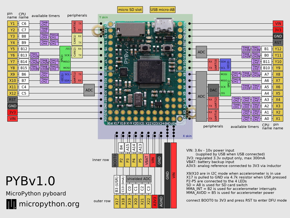
https://learn.sparkfun.com/tutorials/pull-up-resistors Its possible to simply solder the pin "VIN" to the output channels via a resistor. VIN provides 5V directly from the USB. |
|
It wouldn't have to be another branch, adding 2 more channels sounds perfectly backwards compatible (though ofc. they won't work on older devices where they don't exist). If the changes required are really only just that one line, maybe you can submit the relevant pull request. After all, it's your hard work and you should get transparent attribution :) |
|
Actually, wait, would these channels be analog or digital? @faymanns Any idea if the proposed set-up would interfere with the analog solution you implemented via the firmware hack? Or does usage of "VIN" maybe circumvent the need for the firmware hack entirely? |
|
I changed channels 5 and 6 to pin X2 and X4 respectively. Further I changed channels 4, 5 and 6 to open drain and pushed all of this is in a new branch called open_drain (97a6281). The first think you should do however is measure the actual voltage between ground and V+. If I remember correctly it is lower than 5V, something around 4.5V??. It seems like a good idea to use open drain and a pull up resistor, however I think we still won't reach the 5V and we loose the possibility for amplitude modulation(the GPIOs connected to the DAC are not 5V tolerant). |
|
Thanks a lot. I don't have time at the moment to test the hardware and software changes. But I tried triggering the stimulator manually with a voltage source and even ~4.0V is still fine. Maybe for the main version, if anyone ever needs amplitude modulation for the output, I would suggest to keep the pins x4 and x6 for analog output, while x2 and x4 are added for digital TTL pulses. |
So any channels which use the open drain/pull-up resistor model would necessarily be non-amplitude-controllable? Contingent on confirmation that this works (and that 4.5V support precludes amplitude modulation), I believe this can be mainlined by simply adding two output channels 7 and 8, while leaving the original channels and pin assignments untouched. We currently have 3 and only 3 replicas in circulation. If anybody wants to build more, we can think of introducing a clearer organization and breaking backwards-compatibility. We could have, per side:
|
|
@faymanns the |
Yes, for amplitude modulation you need the Digital to Analog converter (DAC) which is not 5V tolerant.
For some reason a connection timed out. I rebuild it successfully. I don't think this is related to the changes I made.
I would like to wait with this until we have tested the pull-up properly, because it means the documentation has to be changed as well. |
Totally agree. Also, it may be wise to submit this to JOSS now, rather than after the next significant update. Since both me, Felix, and Markus will continue to use the device, and you are looking to spend the next years in research as well, it's unlikely the project will flat-out die any time soon, but it looks like future development will be slow, so it could take for ever for this update to actually be finished. Ideally we get the word out first, any maybe then get more uses, which can further speed up testing and development :) |
|
I can't get this open-drain version to work. The Output is constantly at 4.3V (probably the highest that is available from USB) as soon as the pyboard is connected and never changes, not even during outputs. There was probably a bug in boot.py (I sent the changes as pull request), but this didn't solve the problem. I am not really sure whether its a software or hardware problem. This is how I connected the output channel 6 for testing: |

|
@felixsc1 I just measured the output at the bnc using a pull up resistor (10kOhm) like in the schematics above. If I set the value of the pin to 0, I get 0V. If it is set to 1, I measure 4.2V, which is the same voltage as between Vin and ground. Have you tried if 4.3V is sufficient to trigger the stimulator? |
|
@felixsc1 confirmed that 4.2V is enough for him, and seeing that further increases would likely require an external power supply (and thus significant re-engineering of the physical device), we should probably take what we have at this point. What I'd be more interested in is - will the 4.2V depend on the USB port the device is connected to? Will the scaling be done quietly? if so we should definitely document that (i.e. on a 12/24V powered USB ports, 100% amplitude is expected to be 5V, on a 5V powered port 100% amplitude is expected to be 4.9V, on a non-powered port, 100% amplitude will be approx. 4.2V). |
|
@faymanns ping |
|
Finally, I had time to work on this.
I implemented the necessary changes in 6d7cf56
I don't have a 12/24V USB port. In fact, I wasn't even aware that those exist on computers. According to the pyboard docs VIN (what we use for the pull up) can be between 3.6V-10V depending on the power supply. A higher voltage here would also mean a higher value for the pin. |
|
@faymanns could you put together an up-to-date soldering scheme so I can give this a try? |
|
Actually I think this open drain version turned out to be too unpredictable, and therefore I don't use it anymore. Depending on the computer, length of the USB and BNC cables, the output voltage can be very different, it may work on one computer but not on the next... |
|
@felix so you only use the 3.3V output? how different is very different? like what are the maximum and minimum you have obtained from what should nominally have been 100% of 4.2V? |
I've put an updated version of the soldering scheme in the documentation |
Unfortunately, many neurophysiology devices need 5V inputs rather than the 3.3V provided by the pyboard.
E.g. we use this stimulator http://www.ampi.co.il/isoflex.html (input 5-10V) (part of the Master-8, the most widely cited stimulus generator). This stimulus isolator is not triggered by the pyboards low voltage output.
To make the cosplay hardware a viable alternative, I suggest to include in the hardware a 3.3V to 5V "logic level converter" learn.sparkfun.com/tutorials/bi-directional-logic-level-converter-hookup-guide (apparently this doesn't require an additional battery or anything)
The text was updated successfully, but these errors were encountered: