Skip to content
New issue

Have a question about this project? Sign up for a free GitHub account to open an issue and contact its maintainers and the community.

By clicking “Sign up for GitHub”, you agree to our terms of service and privacy statement. We’ll occasionally send you account related emails.

Already on GitHub? Sign in to your account

[feature] Shield/Screen individual cores #330

Open
scottbouch opened this issue Mar 20, 2024 · 8 comments
Open

[feature] Shield/Screen individual cores #330

scottbouch opened this issue Mar 20, 2024 · 8 comments

Comments

@scottbouch
Copy link

Hi, I need to draw a cable where only two cores of a 4 core cable are screened. Presently I have just added a note to the cable properties, but it would be nice to be able to show it with oval shaped rings around the screened cores as you would see in diagrams.

Is there a way to graphically show screens on individual cores?

My example: https://scottbouch.com/tmp/UHF2.html

(Many thanks for this wonderful solution to drawing cables, I love it!)

Cheers, Scott

@scottbouch scottbouch changed the title Shield/Screen individual cores [feature] Shield/Screen individual cores Mar 20, 2024
@kvid
Copy link
Collaborator

kvid commented May 4, 2024

@scottbouch, thank you for sharing your use case. I don't know how to better accomplish your request with the current versions, but maybe a future version can support this. See also #56 for other discussions about complicated cable structures. Before starting a PR adding such a feature, it might be a good idea to discuss here:

  1. How flexible should such a new feature be?
    • Should we support more than one group of shielded wires?
    • Should we support outer levels shielding containing other shield groups and wires?
    • Should we support other shield properties, like e.g. foil, braid, etc.?
    • Should we also support other features that are shared in subsets of wires, like e.g. twisted pairs (until [feature] Ability to specify twisted wires #3 is resolved), wrapped binder groups, etc.?
  2. How can we easily specify it in the YAML input syntax without making it too complicated for the simple cases?
  3. How can we visualize it clearly in the diagram?
  4. Do we need to add any cable shield details in the BOM description?
  5. How much of these features might also be supported for connectors? (See [feature] shield: true for connectors #285)

As suggestions to points 2 and 3 above, see 2 examples below that still allow the original syntax for the simple cases:

cables:
  w:
    colors: [RD, BU, YE, GN]
    shield: [YE, GN]

issue330x gv

cables:
  w:
    colors: [RD, BU, YE, GN]
    shield:
      ShieldP1: [RD, BU]
      ShieldP2: [YE, GN]
      ShieldAll: [ShieldP1, ShieldP2]

issue330y gv

@scottbouch
Copy link
Author

scottbouch commented May 5, 2024

Hi @kvid, thank you so much for responding to this request!

  1. All of your points are valid, and likely to be experienced in real life. When I worked in industrial control systems, we would use long steel wire armoured cross-site cables with an overall foil screen, containing several individually screened twisted pairs or twisted triples (these screens may be electrically isolated from each other and the overall screen). The triple conductor circuits were used where you needed to compensate for volt drop across a long cable length (ie: a sense wire). We didn't mark the armourinng on diagrams, it was an assumed connection of 'safety earth' between pieces of equipment and junction boxes. Some people may wish to use construction details here in the BOM but some may wish to reference a datasheet instead (see point 4). I also have some aircraft multicore cabling where there may be say 12 conductors, each individually screened. So yes, some flexibility to this would be good to suit all eventualities. Speaking of aircraft cables, sometimes in vintage aircraft, an external braid screen is applied over a multicore cable, this is terminated to the shells of connectors at the cable ends. So this additional external screen and fittings/glands would be BOM items external to the cable datasheet. See: https://scottbouch.com/mcfs/elec-connectors/plessey-mk4/plessey-mk4-tools-02.jpg
  2. As I am only a novice with yaml, I shall leave this question to the devs expeexperience!
  3. Your suggested diagrams look good! It would be good if the loop touched the screen 'wire' to show an electrical connection.
  4. The cable datasheet would include screen/shield details, the BOM would only normally include the cable type, reference number, etc.. From which you can find the datasheet. The data sheet would specify foil/braid, drain wire etc... But for a hobbyist with a cable with no part number or datasheet, the ability to manually add some basic construction details may be helpful (also including insulation material foreach layer (for example, PTFE requires different stripping tools to PVC, so these details help to plan the actual making process)
  5. Yes, connectors shells often provide a means of terminating a screen, this could be shown as an 's' terminal as suggested in the other post to land the screen 'wire' on.

Its a bit hard to see in the images, but under the restoration section, the original cable shown has lost its outer jacket, exposing the construction. It has an un-screened red conductor, and individually screened yellow and green. The screen braid is pulled back from the last inch of wire and formed into a 'tail' and given a black insulating sleeve: https://scottbouch.com/mcfs/lightningt5t55/27l-1290-connector-personal-equipment-aircraft-portion.htm
In this cable, the two braid screens are allowed to touch, but its important that they are shown in the diagram as individual screens. (the screened wires here are for a balnced microphone circuit).

Many thanks again for the interest in this request, hopefully I can support further development from my own practical wiring experiences.

@scottbouch
Copy link
Author

scottbouch commented May 6, 2024

In this example, red and blue are not screened, but green and yellow are. The screens are wrapped in a plastic films, so are kept isolated from each other across the length of the cable.

Some versions of this cable type allow the screens to touch.

The option for individual screening of specific cores would be of benefit.

Thanks, Scott

1715000294903
1715000266786

@kvid
Copy link
Collaborator

kvid commented May 6, 2024

@scottbouch, thank you for all the real-world examples that show my suggested examples might be useful and not not too complex.

A consequence of implementing my suggestions above, is that the order of wires within the cable node might need to be reordered from the specified order (and numbering) to be able to draw a loop around consecutive wires.

About point 3, where you wrote "It would be good if the loop touched the screen 'wire' to show an electrical connection.": I agree with you, but I've not yet found a way to obtain that. I used a table with rounded border inside a multi-row cell in the table of wires, and if I reduced the space around the rounded border to make it touch the shield wire below, it would also touch the wire above and the cells on each side. Maybe someone with Graphviz experience might suggest a trick for such a thing?

@scottbouch
Copy link
Author

scottbouch commented May 6, 2024

Hi @kvid , thanks for the work on this.

The order that they appear in the cable node doesn't really matter in this instance as its the colours that matter, but actually this is a DEF-STAN cable, so the green and yellow would end up together anyway. However, I suppose there may be occasions though where a user builds up their own harness including screened and non-screened wires, they may wish to lay them out in a mixed combination to suit their own needs.

Example here of a junction box connector with a mix of screened and un-screened wires, see PL1, SKT1 and SKT2. This is the fixed wiring inside a junction box, but you can also imagine the harnesses plugged in would require the same combination of screened and non-screened wires:

-1-4-3 Ancillary Eq-003b

Regarding the loop around the wires, what you displayed before was good, maybe go with that then in the future see if the gap could be closed up? I.e.: its still a significant improvement!

Worth noting the alternative approach from this above document of dashed parallel lines instead of a loop (dated 1964). But probably best see how it's done in ISO standards, which may well be a loop as discussed.

Thanks again, Scott

@kvid
Copy link
Collaborator

kvid commented May 7, 2024

@scottbouch wrote:

[...]
Regarding the loop around the wires, what you displayed before was good, maybe go with that then in the future see if the gap could be closed up? I.e.: its still a significant improvement!

I agree - we can probably live with the small gap until someone finds a way to improve it.

Worth noting the alternative approach from this above document of dashed parallel lines instead of a loop (dated 1964). But probably best see how it's done in ISO standards, which may well be a loop as discussed.

The dashed parallel lines could be an alternative visualization for individual screened wires, but I'm not sure how it can be used to show that multiple wires have a common shield.

I've not found "how it's done in ISO standards", but I found examples using dashed loops around a single wire or group of wires and one with references to IEC 60617-2019 and IEEE Std 315-1993. I also have seen a copy of the latter and can confirm it uses dashed loops around the wires. It seems IEC uses a dashed circle around a single wire, and a dashed circle outside a group of wires with arrows into each of the shielded wires. The latter alternative allows unshielded wires in-between shielded wires in the same group (see note A5 at the last linked page), but it might be a bit hard to read. IEEE allows separate dashed loops to be connected with a dashed line when not all wires in the common shield are adjacent in the diagram, but the IEC alternatives are also allowed.
shielding
Both arrows into each wire and connected loops (the left variations in the figure above) can be used to avoid reordering wires in the cable node, but they both might also be challenging to create with the limited Graphviz syntax.

I've tried using dashed loops in one of my examples, and I made one of the loops with a thicker line (using 2 pt which is equal to the shield connection spline thickness) to see if that is better:
issue330y2 gv

Click to expand Graphviz .gv file source code
graph {
// Graph generated by WireViz 0.4-dev (and manually modified to add multiple wire shields)

// https://github.com/formatc1702/WireViz

   graph [bgcolor="#FFFFFF" fontname=arial nodesep=0.33 rankdir=LR ranksep=2]
   node [fillcolor="#FFFFFF" fontname=arial height=0 margin=0 shape=none style=filled width=0]
   edge [fontname=arial style=bold]
   x1 [label=<
<table border="0" cellspacing="0" cellpadding="0">
<tr><td>
 <table border="0" cellspacing="0" cellpadding="3" cellborder="1"><tr>
  <td balign="left">x1</td>
 </tr></table>
</td></tr>
<tr><td>
 <table border="0" cellspacing="0" cellpadding="3" cellborder="1"><tr>
  <td balign="left">5-pin</td>
 </tr></table>
</td></tr>
<tr><td>
 <table border="0" cellspacing="0" cellpadding="3" cellborder="1">
  <tr>
   <td port="p1r">1</td>
  </tr>
  <tr>
   <td port="p2r">2</td>
  </tr>
  <tr>
   <td port="p3r">3</td>
  </tr>
  <tr>
   <td port="p4r">4</td>
  </tr>
  <tr>
   <td port="p5r">5</td>
  </tr>
 </table>
</td></tr>
</table>
> fillcolor="#FFFFFF" shape=box style=filled]
   x2 [label=<
<table border="0" cellspacing="0" cellpadding="0">
<tr><td>
 <table border="0" cellspacing="0" cellpadding="3" cellborder="1"><tr>
  <td balign="left">x2</td>
 </tr></table>
</td></tr>
<tr><td>
 <table border="0" cellspacing="0" cellpadding="3" cellborder="1"><tr>
  <td balign="left">5-pin</td>
 </tr></table>
</td></tr>
<tr><td>
 <table border="0" cellspacing="0" cellpadding="3" cellborder="1">
  <tr>
   <td port="p1l">1</td>
  </tr>
  <tr>
   <td port="p2l">2</td>
  </tr>
  <tr>
   <td port="p3l">3</td>
  </tr>
  <tr>
   <td port="p4l">4</td>
  </tr>
  <tr>
   <td port="p5l">5</td>
  </tr>
 </table>
</td></tr>
</table>
> fillcolor="#FFFFFF" shape=box style=filled]
   edge [color="#000000:#ff0000:#000000"]
   x1:p1r:e -- w:w1:w
   w:w1:e -- x2:p1l:w
   edge [color="#000000:#0066ff:#000000"]
   x1:p2r:e -- w:w2:w
   w:w2:e -- x2:p2l:w
   edge [color="#000000:#ffff00:#000000"]
   x1:p3r:e -- w:w3:w
   w:w3:e -- x2:p3l:w
   edge [color="#000000:#00ff00:#000000"]
   x1:p4r:e -- w:w4:w
   w:w4:e -- x2:p4l:w
   edge [color="#000000"]
   x1:p5r:e -- w:ws1:w
   x1:p5r:e -- w:ws2:w
   w:ws:e -- x2:p5l:w
   w [label=<
<table border="0" cellspacing="0" cellpadding="0">
<tr><td>
 <table border="0" cellspacing="0" cellpadding="3" cellborder="1"><tr>
  <td balign="left">w</td>
 </tr></table>
</td></tr>
<tr><td>
 <table border="0" cellspacing="0" cellpadding="3" cellborder="1"><tr>
  <td balign="left">4x</td>
  <td balign="left">+ 3xS</td>
 </tr></table>
</td></tr>
<tr><td>
 <table border="0" cellspacing="0" cellborder="0">
  <tr><td>&nbsp;</td></tr>
  <tr>
   <td rowspan="17">
    <table border="0" cellspacing="2" cellborder="2">
     <tr><td style="rounded,dashed">&nbsp;</td></tr>
    </table>
   </td>
   <td rowspan="6">
    <table border="0" cellspacing="2" cellborder="1">
     <tr><td style="rounded,dashed">&nbsp;</td></tr>
    </table>
   </td>
   <td>x1:1</td>
   <td>
    1:RD
   </td>
   <td>x2:1</td>
  </tr>
  <tr>
   <td colspan="5" border="0" cellspacing="0" cellpadding="0" port="w1" height="6">
    <table cellspacing="0" cellborder="0" border="0">
     <tr><td colspan="3" cellpadding="0" height="2" bgcolor="#000000" border="0"></td></tr>
     <tr><td colspan="3" cellpadding="0" height="2" bgcolor="#ff0000" border="0"></td></tr>
     <tr><td colspan="3" cellpadding="0" height="2" bgcolor="#000000" border="0"></td></tr>
    </table>
   </td>
  </tr>
  <tr>
   <td>x1:2</td>
   <td>
    2:BU
   </td>
   <td>x2:2</td>
  </tr>
  <tr>
   <td colspan="5" border="0" cellspacing="0" cellpadding="0" port="w2" height="6">
    <table cellspacing="0" cellborder="0" border="0">
     <tr><td colspan="3" cellpadding="0" height="2" bgcolor="#000000" border="0"></td></tr>
     <tr><td colspan="3" cellpadding="0" height="2" bgcolor="#0066ff" border="0"></td></tr>
     <tr><td colspan="3" cellpadding="0" height="2" bgcolor="#000000" border="0"></td></tr>
    </table>
   </td>
  </tr>
  <tr><td>&nbsp;</td></tr>
  <tr>
   <td>x1:5</td>
   <td>ShieldP1</td>
   <td></td>
  </tr>
  <tr><td colspan="5" cellpadding="0" height="2" bgcolor="#000000" border="0" port="ws1"></td></tr>
  <tr><td>&nbsp;</td></tr>
  <tr>
   <td rowspan="6">
    <table border="0" cellspacing="2" cellborder="1">
     <tr><td style="rounded,dashed">&nbsp;</td></tr>
    </table>
   </td>
   <td>x1:3</td>
   <td>
    3:YE
   </td>
   <td>x2:3</td>
  </tr>
  <tr>
   <td colspan="5" border="0" cellspacing="0" cellpadding="0" port="w3" height="6">
    <table cellspacing="0" cellborder="0" border="0">
     <tr><td colspan="3" cellpadding="0" height="2" bgcolor="#000000" border="0"></td></tr>
     <tr><td colspan="3" cellpadding="0" height="2" bgcolor="#ffff00" border="0"></td></tr>
     <tr><td colspan="3" cellpadding="0" height="2" bgcolor="#000000" border="0"></td></tr>
    </table>
   </td>
  </tr>
  <tr>
   <td>x1:4</td>
   <td>
    4:GN
   </td>
   <td>x2:4</td>
  </tr>
  <tr>
   <td colspan="5" border="0" cellspacing="0" cellpadding="0" port="w4" height="6">
    <table cellspacing="0" cellborder="0" border="0">
     <tr><td colspan="3" cellpadding="0" height="2" bgcolor="#000000" border="0"></td></tr>
     <tr><td colspan="3" cellpadding="0" height="2" bgcolor="#00ff00" border="0"></td></tr>
     <tr><td colspan="3" cellpadding="0" height="2" bgcolor="#000000" border="0"></td></tr>
    </table>
   </td>
  </tr>
  <tr><td>&nbsp;</td></tr>
  <tr>
   <td>x1:5</td>
   <td>ShieldP2</td>
   <td></td>
  </tr>
  <tr><td colspan="5" cellpadding="0" height="2" bgcolor="#000000" border="0" port="ws2"></td></tr>
  <tr><td>&nbsp;</td></tr>
  <tr>
   <td rowspan="1">&nbsp;</td>
   <td></td>
   <td>ShieldAll</td>
   <td>x2:5</td>
  </tr>
  <tr><td colspan="5" cellpadding="0" height="2" bgcolor="#000000" border="0" port="ws"></td></tr>
  <tr><td>&nbsp;</td></tr>
 </table>
</td></tr>
</table>
> fillcolor="#FFFFFF" shape=box style=filled]
}

@scottbouch
Copy link
Author

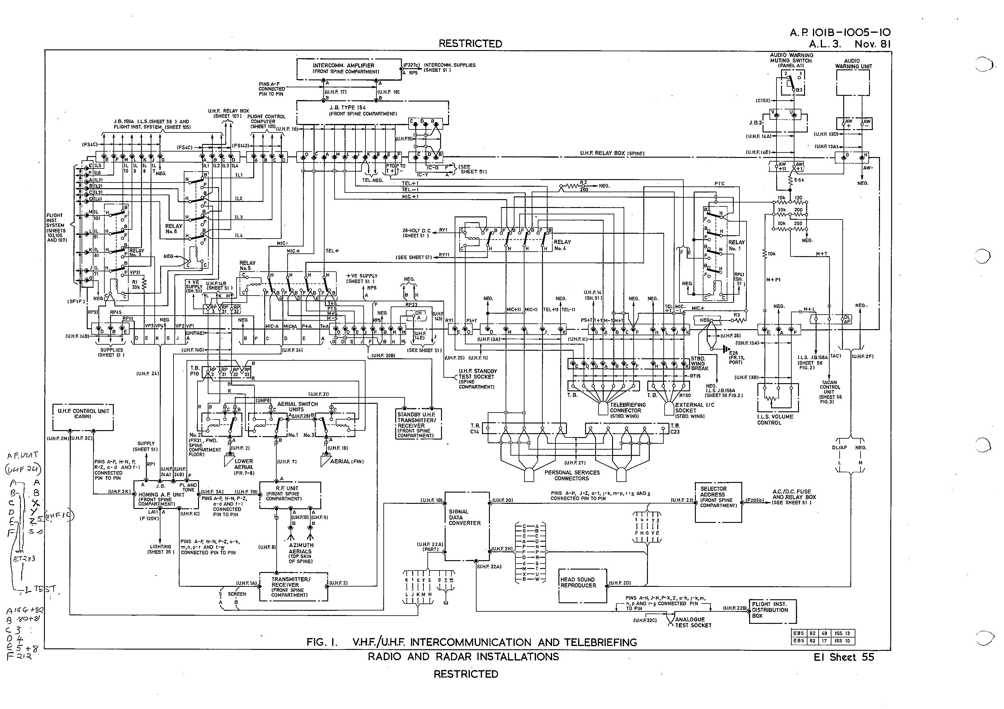
Hi @kvid, that is a very good website, thanks.

Overall, it would be good to implement whats presently easy or possble, with a 'TODO' list for future improvements.

Another take on it, in this example, the screens are shown as single circles connected by a line, even if they are drawn next to each other. These mic/tel wires are the exact wiring type I shred an image of, for aircraft communication circuits.

screenshot20240508_083959228
Source: https://scottbouch.com/mcfs/lightningt5t55/docs/ap101b-1005-10-sh55-fig1-al3-nov81-vhf-uhf-intercommunication-telebriefing.jpg

Maybe it would be good if possible to ideally give the user the option to connect circles with lines, or to draw ovals enveloping several wires, this gives freedom.

Also worth noting that the multiple arrows are used in this drawing, but not for screens, instead are used to provide wiring harness identification.

Cheers, Scott

@scottbouch
Copy link
Author

scottbouch commented May 8, 2024

I have just been reading IEEE 315-1975; it turns out the multiple headed arrows can be used for a variety of reasons, such as the application of screening or identification nomenclature as shown in these posts, plus the arrows can also be used to assign wires to twisted pairs.

It also defines long dashes for screening/shielding:

image

Here the arrows are used to show which conductors are shielded (3 out of 7), plus we are into the use of circles and ovals:

image

Note how the solid loop (last examples below) is used to identify multicore cables, not screening:

image

The next section of the standard is onto RF coaxial cables, but that can wait for a future date!

(I don't have a copy of IEC 60617 for comparison.)

Cheers, Scott.

Sign up for free to join this conversation on GitHub. Already have an account? Sign in to comment
Labels
None yet
Projects
None yet
Development

No branches or pull requests

2 participants