Skip to content
New issue

Have a question about this project? Sign up for a free GitHub account to open an issue and contact its maintainers and the community.

By clicking “Sign up for GitHub”, you agree to our terms of service and privacy statement. We’ll occasionally send you account related emails.

Already on GitHub? Sign in to your account

Force connector to wire connections to the same side #293

Open
martonmiklos opened this issue Sep 15, 2022 · 23 comments
Open

Force connector to wire connections to the same side #293

martonmiklos opened this issue Sep 15, 2022 · 23 comments

Comments

@martonmiklos
Copy link
Contributor

Hello all,

I am trying to document a H topology cable:
kép
From the following source:

https://gist.github.com/martonmiklos/8603dcaaebea8eea07143e39b3de4fa0

It renders what I want to make, but the arranging is not quite as descriptive as it should.

Is there any way to force the +12V out 2 and GND out 2 connctors:
kép

To force the wire entry to one side like happens on the +12V out 1 and GND out 1?
kép

@kvid
Copy link
Collaborator

kvid commented Sep 15, 2022

Do you perhaps want a layout similar to Tutorial 7 with all connectors along the left and right sides with zig-zag cables daisy-chained between them? If so, choose alternating sides for each connector in the daisy-chain, and specify all connections from the left connector via the cable to the right connector.

In your use case, you might try the "in 2" connectors left, then the "out 2" and "in 1" connectors right, and finally "out 1" connectors left, but swapping left and right sides should also work.

@kvid
Copy link
Collaborator

kvid commented Sep 16, 2022

My suggestion above would look something like this:
issue293ys
The main difference from the original source file is the order of elements within some of the connections. I replaced the original connections with these:

connections:
  # hosszú szár normál #1
  -
    - ['+12V out 1', 'GND out 1', 'XLiNE out 1']
    - '500 mm H hosszú szára #1': [1-3]
    - ['+12V in 1', 'GND in 1', 'XLiNE in 1']

  # hosszú szár normál #2
  -
    - ['+12V in 2', 'GND in 2', 'XLiNE in 2']
    - '500 mm H hosszú szára #2': [1-3]
    - ['+12V out 2', 'GND out 2', 'XLiNE out 2']

  # átkötő
  -
    - ['+12V out 1', 'GND out 1']
    - '300 mm átkötő': [1-2]
    - ['+12V out 2', 'GND out 2']
  • I have simplified the source by joining all wires of a cable in the same connection entry, and dropped the redundant pin 1 specifier for simple 1-pin connectors, but none of that change the output in any way.
  • I have reversed the order of connection entries for cables hosszú szára #1 and átkötő to reverse their direction in the diagram and thereby obtain the zig-zag cable pattern as in Tutorial 7.

@martonmiklos
Copy link
Contributor Author

Many thanks for the hint @kvid !

I was not aware of the ordering importance!

Do you know if the orientation of cable exit ports on the boxes could be set somehow?

The cable in the question is rather a H cable than a Z in reality, and it could have added value to visualize that way.

@kvid
Copy link
Collaborator

kvid commented Sep 16, 2022

  1. The left or right exit port is determined by the order of connection entries: For each wire spline between two connection entries, it goes from the right side of one entry to the left side of the next entry.

  2. When you describe the harness as an H, does that mean the middle cable is actually connected between the middle points of the two other cables, and not the connectors in either end? If so, then you might consider including those middle points in the harness as 3-way wire junctions, but all cable boxes in the diagram will have a left-right orientation, so a true H with both horizontal and vertical cables might not be so easy to obtain.

@nindroz
Copy link

nindroz commented May 15, 2024

For CAN wiring purposes I was looking to genuinely force wires out of one side, does anyone know if its doable?

@kvid
Copy link
Collaborator

kvid commented May 15, 2024

@nindroz wrote:

For CAN wiring purposes I was looking to genuinely force wires out of one side, does anyone know if its doable?

I know what a CAN bus is, but I don't really understand what you're trying to achieve. Can you show here what you've tried, and then explain what you would like to be different. If your problem has very little in common with what was asked or suggested here, you should consider creating a new issue.

@martonmiklos
Copy link
Contributor Author

@nindroz wrote:

For CAN wiring purposes I was looking to genuinely force wires out of one side, does anyone know if its doable?

I know what a CAN bus is, but I don't really understand what you're trying to achieve.

If I guess well he is wiring the CAN bus to a node back and forth (by connecting two wires to a same pin). To describe what is done physically the wires needs to be connected on the same side to the connector not the opposite.

@nindroz
Copy link

nindroz commented May 16, 2024

Essentially, I need the green and yellow wires going into the left side of the TT_FR connector. It needs to be on the left of both connectors as they recieve the other 2 wires (power and ground from a connector the far left)
SCR-20240515-nz6

@kvid
Copy link
Collaborator

kvid commented May 16, 2024

@nindroz wrote:

Essentially, I need the green and yellow wires going into the left side of the TT_FR connector. It needs to be on the left of both connectors as they recieve the other 2 wires (power and ground from a connector the far left)

After you've decided the left-right order of your cables and connectors, then specify connections ordered from left to right. See also point 1 in #293 (comment).

@nindroz
Copy link

nindroz commented May 17, 2024

For the CAN connection, there is no left and right for the connectors. They esssentially need to be parallell. I specifically need the green and yellow wire in the picture to be on the left of the TT_FR connector and the left of the steering connector.

@kvid
Copy link
Collaborator

kvid commented May 18, 2024

Sorry, but I don't understand which end of the TT_FRC bundle that should be connected to the TT_FR connector. This connector seems to be connected to both ends, and normally that doesn't make sense.

@tobiasfalk
Copy link

@nindroz could you give the wirvize code? this may allow experimenting to look what you want.

@nindroz
Copy link

nindroz commented May 21, 2024

  #front bulkhead
  X:
    style: simple
    autogenerate: true
    type: " "
    ignore_in_bom: true
  F:
    category: ferrule
    type: ferrule
    style: simple
  FB:
    pincount: 30
    pinlabels:
      [
        24V PCBA,
        5V_APPS1,
        5V_APPS2,
        5V,
        12V,
        GND,
        GND,
        5V_GND,
        5V_GND_APPS1,
        5V_GND_APPS2,
        SDC_In,
        SDC_out,
        CANL_CTRL,
        CANH_CTRL,
        CANH_PT,
        CANL_PT,
        Analog_In_PSI_F,
        EGZ_Button,
        INV_Reset_Button,
        Analog_In_SPS1,
        Analog_In_SPS2,
        Analog_In_APPS1,
        Analog_In_APPS2,
        Analog_In_PSI_R,
      ]
    type: FGN.3M.330.XLCT 30-pin LEMO
    subtype: male
  Dash:
    pincount: 4
    pinlabels: [24V_PCBA, 24V_GND, CANH_PT, CANL_PT]
    type: 4-Pin Molex
  SPS:
    pincount: 6
    pinlabels: [5V, 5V_GND, Analog_In_SPS1, 5V, 5V_GND, Analog_In_SPS2]
    type: 6-Pin souriau
  Steering:
    pincount: 6
    pinlabels:
      [24V_PCBA, 24V_GND, CANH_CTRL (CAN TERMINATE), CANL_CTRL (CAN TERMINATE)]
    type: 6 Pin Souriau
  PSI_F:
    pincount: 5
    pinlabels: [5V, 5V_GND, Analog_In_PSI_F]
    type: 5 Pin Souriau
  PSI_R:
    pincount: 5
    pinlabels: [5V, 5V_GND, Analog_In_PSI_R]
    type: 5 Pin Souriau
  TT_FR:
    pincount: 6
    pinlabels: [12V, GND, CANH_CTRL, CANL_CTRL, CANH_CTRL, CANL_CTRL]
cables:
  DashC:
    category: bundle # bundle
    gauge: 24
    colors: [VT, BK, YE, GN] # custom colors, wirecount is implicit
  SPSC:
    category: bundle # bundle
    gauge: 24
    colors: [VT, GY, GN, VT, GY, GN]
  SteeringC:
    category: bundle # bundle
    gauge: 24
    colors: [VT, BK, BU, WH]
  PSIFC:
    category: bundle # bundle
    gauge: 24
    colors: [VT, GY, GN]
  PSIRC:
    category: bundle # bundle
    gauge: 24
    colors: [VT, GY, GN]
  TT_FRC:
    category: bundle
    gauge: 24 AWG
    colors: [VT, GY, GN, YE, GN, YE]
  TEST:
    colors: [YE, GN] # custom colors, wirecount is implicit
connections:
  - - FB: [1, 6]
    - DashC: [1, 2]
    - Dash: [1, 2]
  - - FB: [4, 4, 20, 21, 8, 8]
    - SPSC: [1, 4, 3, 6, 2, 5]
    - SPS: [1, 4, 3, 6, 2, 5]
  - - FB: [1, 7]
    - SteeringC: [1, 2]
    - Steering: [1, 2]
  - - FB: [5, 8, 17]
    - PSIFC: [1, 2, 3]
    - PSI_F: [1, 2, 3]
  - - FB: [5, 8, 18]
    - PSIRC: [1, 2, 3]
    - PSI_R: [1, 2, 3]
  - - FB: [5, 7]
    - TT_FRC: [1, 2]
    - TT_FR: [1, 2]
  - - TT_FR: [3, 4]
    - TT_FRC: [3, 4]
    - [X, X]
    - SteeringC: [3, 4]
    - Steering: [3, 4]

  # - # connect the shielding to a pin
  #   - X1: 1
  #   - W1: s
tweak:
  override:
    # Note that these autogenerated designators might be generated
    # differently in future versions of WireViz. Define each splice
    # manually with unique designators to be safer.
    _X_1:
      shape: point
    _X_2:
      shape: point
    _X_3:
      shape: point
  append: |-
    // Tweaking splice nodes to keep close to each other
    subgraph cluster1 {
      color=white // Same as background to hide the surrounding frame
      _X_1
      _X_2
      _X_3
    }

@tobiasfalk
Copy link

@nindroz are any of these three that what you meant?
1:
test3_aZ

2:
test3_bZ

3:
test3_cZ#

@nindroz
Copy link

nindroz commented May 22, 2024

The last one!

@EloiVilalta
Copy link

Hello, exactly what I was looking for!
Right now we can only do "right to left" connections following the Connector-Cable-Connector method. But @tobiasfalk , in the "2" you got "left" TT_FRC to "left" TT_FR and in "3" you got "left" TT_FRC to "left" _X_3. How did you do it?

The daisy chain example is changing the connectors from left to right, but I think that @nindroz and me need the connectors always on the same side.
This is what I'm trying to achieve (in vertical position):
image
Here is another example of what I mean (in horizontal position, but we can't make vertical connections, right?).

I understand that we'll have to place the cable ("TT_FRC" in this case) between the connectors (in my case the "TT_FR" and "_X_3" are named "Y/T splice.1" and "Y/T splice.2"), but at some point we need the "left to left" connection as you did.

Let us know how you did it please! :D

Thanks!
Eloi

PD: vertical connections would be awesome, I did not checked if it's already possible or not.

@tobiasfalk
Copy link

Hello, exactly what I was looking for!
Right now we can only do "right to left" connections following the Connector-Cable-Connector method. But @tobiasfalk , in the "2" you got "left" TT_FRC to "left" TT_FR and in "3" you got "left" TT_FRC to "left" _X_3. How did you do it?

I did this by editing the .gv output to give a better visualisation of what @nindroz meant.

@EloiVilalta
Copy link

EloiVilalta commented Jun 5, 2024

@nindroz , I finally got it. Let me explain how I did it so everyone can solve this issue with a super basic example:

"file_name".yml:

connectors:
  C1:
    style: simple
    type: Connector
  C2:
    style: simple
    type: Connector      
cables:  
  W1:
    wirecount: 1
    show_name: false
    show_wirecount: false
    colors: [RD]

connections:
  -
    - C1: [1]
    - W1: [1]
    - C2: [1]

This is what we get:
image

As .gv file is not generated nowadays by default we need to add -f g after wireviz "file_name".yml to produce as output the .gv file, so wireviz "file_name".yml -f g.

With the .gv open, you have to search and modify the second connection:

 > fillcolor="#FFFFFF" shape=box style=filled]
  edge [color="#000000:#ff0000:#000000"]
  C1:e -- W1:w1:w
-  W1:w1:e -- C2:w
+  W1:w1:w -- C2:w
  W1 [label=<

The "e" means "right", and the "w" means "left". (EDIT: "e" means East, "w" means West, this is the position where the "line" starts at the "box", check GraphViz documentation)
Save it.
Use dot -O -Tpng "new_file_name.gv" to generate the image again.
Now we have this new .png image:
image

Try to imagine it as:
image

Hope it helps!

@tobiasfalk
Copy link

Yes that is basically what I did in the .gv output

@EloiVilalta
Copy link

EloiVilalta commented Jun 5, 2024

Sure @tobiasfalk , I previously asked how to do it, but ended up learning it and sharing how to do it ;) Thanks!

For everybody,

In the example above I changed a cable connection, but in case you want to change a connector (Splice), keep in mind there is more "info" in the .gv that has to be changed. I only could go from this:
image
To this:
image

I had to change, as explained before, the "e" to "w":

 > fillcolor="#FFFFFF" shape=box style=filled]
  edge [color="#000000:#ff0000:#000000"]
-  JB3:p1r:e -- W3:w1:w
+  JB3:p1l:w -- W3:w1:w
  W3:w1:e -- JB4:p1l:w
  edge [color="#000000:#8000ff:#000000"]
-  JB3:p2r:e -- W3:w2:w
+  JB3:p2l:w -- W3:w2:w
  W3:w2:e -- JB4:p2l:w
  edge [color="#000000:#ffffff:#000000"]
-  JB3:p3r:e -- W3:w3:w
+  JB3:p3l:w -- W3:w3:w
  W3:w3:e -- JB4:p3l:w
  edge [color="#000000:#000000:#000000"]
-  JB3:p4r:e -- W3:w4:w
+  JB3:p4l:w -- W3:w4:w
  W3:w4:e -- JB4:p4l:w
  edge [color="#000000"]
-  JB3:p5r:e -- W3:ws:w
+  JB3:p5l:w -- W3:ws:w
  W3:ws:e -- JB4:p5l:w
  W3 [label=<

And another time for the second cable in my code.

Keep in mind to also change the "r" to "l", as it refers to the "numbered box", if you don't change the "r" to "l" you will get the "left" side of the "left" box:
image

I would suggest to "redistribute/regroup" the cables and connectors prior the modification of the .gv file using this tweak.

Anyone know how to tweak (override/append) the "left/right" issue inside the .yml file?
Thanks!

@kvid
Copy link
Collaborator

kvid commented Jun 5, 2024

@EloiVilalta wrote:

[...]
The daisy chain example is changing the connectors from left to right, but I think that @nindroz and me need the connectors always on the same side. This is what I'm trying to achieve (in vertical position):

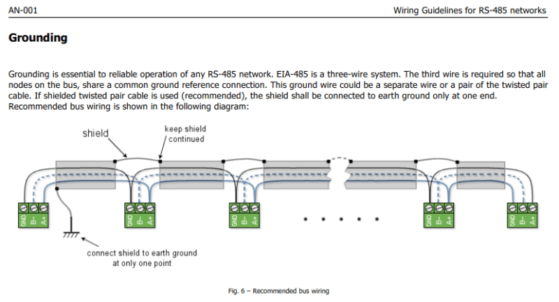
If what you really need, is daisy-chaining bus wires between a series of connectors, why do you require all wires connecting from the same side?

Here is another example of what I mean (in horizontal position, but we can't make vertical connections, right?).

The RS485 use case you link to, can easily be implemented (similarly to tutorial04) in WireVis like this:
issue293-rs485

connectors:
  X:
    pinlabels: [GND, B-, A+]
    color: GN
  J:
    type: Junction
    style: simple
cables:
  W:
    colors: [BN, YE, GN]
    shield: true
connections:
  -
    - X.: [1-3]
    - W.W1: [1-3]
    - X.: [1-3]
    - W.W2: [1-3]
    - X.: [1-3]
  -
    - J.
    - W1: [s]
    - J.
    - W2: [s]
    - J.

The number of connector can easily be expanded, but when the number of connector increases, this diagram gets very wide. Then I would rather recommend zig-zag daisy-chaining like in tutorial07 to obtain a more compact diagram. Electrically, it doesn't matter which of these drawing techniques are used. The connections are the same, just drawn in a different layout and order to help readability.

Forcing wires around to the opposite side, like in some of the examples above, will only harm readability, IMHO.

@EloiVilalta
Copy link

Thank you @kvid , my problem is that from the " bus connections" there is custom cables going to the devices, with different pinout, different colors...
I'm designing a redundant bus with differents Y splices that needs to be resin moulded, some with two cables inside, some with just one, some with parallel cables, some with cables that joins to the "bus connection".

Anyway, I've been checking all day what GraphViz is capable of doing and you can only choose ONE direction.
Unless we can do a subgraph with different direction settings (I tried it and could not make it because it gets overwritten), we cannot do it... This guy was trying the same on stackoverflow.

why do you require all wires connecting from the same side?

The schematics had been like this since the beginning of the project, and change it now it's pretty difficult. I wanted to place the detailed cables on top of the actual schematic.

Another problem I faced is that the cables will choose to go over or under the "box" depending if they start over the center or under it. Unless I put the "picture" on top and all the cables goes at the bottom, it's impossible to make it look fancy, here is the example:
image
I could not figure it out any attribute to force to go over or under the node. It looks like (not working on DOT), there is this option that you can edit the "splines"...

I'll have to make it Zig-Zag. But I'm really happy about what I've learnt today! And I'm pretty sure I'll use GraphViz more often!

BTW, I'm using http://magjac.com/graphviz-visual-editor/ to edit the .gv and see the changes in real time.

@martinrieder
Copy link

FYI: Graphviz comes with a tool called gvpr that can be used to post-process the graph. Just a hint that it is worth taking a look...
https://graphviz.org/pdf/gvpr.1.pdf

Sign up for free to join this conversation on GitHub. Already have an account? Sign in to comment
Labels
None yet
Projects
None yet
Development

No branches or pull requests

6 participants